Miller Capacitance, Power MOSFETs, and Obscure Problems
When I started to design my BLDC motor controller, I was expecting things to go fast and clean. After all, it’s mostly plugging prefab modules together. Surely designing the PCB is the only real challenge, right?
Well it turns out power electronics is hard. Explodes in your face levels of hard. I’ve already learned some stark lessons about just how much can go wrong: component oversights, bootstrapping troubles, and the perils of trying to do too much at once. Perhaps it would be better to call this project “Things that go wrong with power MOSFETs”.
Today we add yet another, rather obscure problem with power inverters: Miller capacitance. Usually we talk about Miller capacitance in the context of amplifiers, where it greatly reduces bandwidth. In inverters this effect still exists, but it’s usually secondary to other concerns. But, there’s a particular issue power inverters have with Miller capacitance.
After a mysterious gate blowout on an otherwise functional BLDC inverter, I was compelled to go down the rabbit hole of Miller capacitance in power MOSFET circuits. Despite being a pretty important issue that can explode an otherwise functional circuit, it’s surprisingly hard to find good information. The good news is that Miller coupling can be managed with good design practices. Retrofitting protection isn’t easy (PCB modding never is), but you can do it.
The Long, Sordid Story so Far
Several years ago, I got it in my head that it would be cool to build a BLDC inverter. I had all kinds of hopes and dreams about what I could do with it. I spent quite a lot of time and effort building the first prototype. In my hubris, I plugged it straight into the 48V battery pack I was planning to use.
It exploded on the first test.
The second version also exploded, which led me to a total redesign using the MC33035 (see that story here). This third version did work- but only if it was already running. A quick patch to fix up an embarrassing oversight later, and it worked just fine. Worked just fine on my low-voltage, current limited, bench supply. Not the 48V battery that exploded the last two prototypes.
Having solved the most serious problems in the inverter, I knew I would eventually have to test it at full power. I put it off through the winter, but it’s summer and I kind of need a working BLDC controller now. Knowing that this circuit has a history of exploding, I chose to power it up using a 48V power supply that has inherent overcurrent protection. When it didn’t explode I was emboldened to push it to the limit. After all, I clearly haven’t learned my lesson yet.
Everything started out fine. The motor spun, accelerated, decelerated, and stopped as expected. Okay, there’s some weird stuttering when the throttle is at minimum, but that’s because the throttle doesn’t zero out properly. At least I think that’s the problem.
Then I tried to do a hard acceleration and the whole thing just shut down. No amount of tweaking, resetting, or unplugging could get the inverter to any degree of functionality. Probing revealed that, once again, I had blown several of the MOSFETs. I couldn’t really explain why they blew, but the gate had clearly blown out. This is a very different failure mode than a drain-source short. I had overlooked something in the gate circuit. Something quite obscure, as it turns out.
Miller Capacitance and Power MOSFETs
Whenever you have an active amplifier, such as a power transistor, you have to deal with the Miller effect. In short, the Miller effect states that any capacitance between input and output appears larger than it is. Specifically the input capacitance appears to be the Miller capacitance multiplied by the gain. Gate-drain capacitance is therefore frequently called Miller capacitance.
In power circuits, the Miller effect does two things. First it limits switching speed. That’s not that interesting for my BLDC inverter, since it operates at fairly low frequencies that the IRL520 should be able to handle. No, it’s the second property that’s interesting: it couples charge from output to input.

MOSFETs gates look like capacitors, electrically speaking. Put charge into a capacitor, it’s voltage goes up. Add in an inductive load causing all kinds of weird voltage/current spikes, and you get problems. Miller coupling can cause the MOSFET to turn on at the wrong time, shorting out the inverter leg. Exceed the maximum Vgs voltage, and you instantly blow out the gate. These effects tend to happen sequentially. Both MOSFETs in the inverter leg get blown out as a result.
While you would hope all MOSFET drivers are designed to cope with this, most of them aren’t. Why? No idea. Probably a mix of design inertia and “stop helping me” syndrome. Protecting the gate is usually your responsibility.
Solving the Charge Coupling Problem
The most common solution to deal with gate overvoltage is to simply put a Zener diode between the gate and source. That would avoid the catastrophic gate breakdown. Here’s the rub though: I don’t have any suitable Zeners- I checked. It also doesn’t solve any problems with the gate floating.
An alternative, often used with the Zener, but sometimes omitted, is to put a simple resistor between gate and source. This limits the overall voltage on the gate (not as much as a Zener, but better than nothing), as well as ensuring charge that leaks in while the MOSFET is supposed to be off is discharged. I have plenty of resistors, so it’s worth trying.

It took me quite a long time to find any real information on this coupling phenomenon. Apparently it’s well known as long as you’re a lifelong power electronics engineer. The resistor trick also took a while to find. It may have been more common back in the day, but it’s tough to find now.
BLDC Controller Hasty Modifications
My first problem was replacing the burned out MOSFETs. I always try to order a few extra parts for exactly this reason. Guess who decided to only order six IRF520 MOSFETs as part of a questionable cost cutting measure? IRF520s were apparently expensive enough I skimped out. You pay plenty for the good ones.
Undeterred, I switched over to the IRF730, which I have plenty of. I vaguely remember choosing not to use them before, but I still haven’t learned my lesson. Besides, at this point I don’t have much to lose. Whichever way you slice it, if this mod doesn’t work I’m going to have to do a total rebuild with a spare PCB.

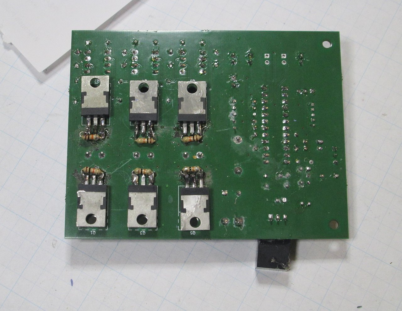
An 1/8th watt through-hole resistor fits nicely across the source/gate pins of a TO-220.

Pretty nasty when you look closer. Good thing this is on the bottom.

Behold, the price of hubris.
(Approximately 10.88 USD in 2023)
My soldering iron is on the fritz again, so it ran hot while doing this mod. I definitely damaged the PCB, but the new IRF730s got in without completely destroying the whole lot.
Having modded in the new MOSFETs, I immediately started testing. Wouldn’t you know it, I blew the new MOSFETs out! Even faster than before! Oh no!
Here’s the thing though: it wasn’t gate blowout that killed them. Two clues led me to that conclusion. First, the top MOSFET failed with a drain-source short, but not a gate short. Second, the MOSFETs were in different legs of the H bridge. Gate blowout usually destroys both MOSFETs in the same leg.
Remember how I said I vaguely remembered passing over the IRF730? Well, it turns out the IRF730 has four times the Rds of the IRF520. That means it will run four times hotter than the IRF520. Couple that with a half-assed heatsink job, and it’s clear they just failed due to overheating. I guess that’s a good thing? You know, relatively speaking?
If you’re wondering how to estimate power MOSFET dissipation, check out this article from Analog.
Using the values for the IRF730 @ 5A, I get around 40 to 50 watts. Ouch!
After replacing the MOSFETs (again), I ensured the heatsink was properly installed. A brief test proved that the IRF730 based inverter ran much hotter. Post test probing proved that everything was still in working order. Clearly I need to move to a better heatsink.
Finishing Up
Power electronics is hard. I know I said that already, but it bears repeating: power electronics is hard. Part of the problem is that power electronics tend to fail catastrophically. Said catastrophic failure tends to cause other things to fail catastrophically. Occasionally things catch fire, explode, catch fire and explode, or explode in flames. The likeliness of this happening seems strongly correlated to how expensive those things are.
I don’t know how well the new resistors will dissipate coupled gate charge. They’re much better than nothing, but I worry they won’t be sufficient. In the event the IRF730’s burn out (let’s face it, a reasonably likely outcome) I’m going to switch over to MOSFETs with built-in gate Zeners. Assuming I don’t just throw everything out and restart.
Hard acceleration was what caused the blowout to begin with. This has made me rethink how my control circuit is set up. Acceleration control would also limit inductive spikes, which are what’s getting coupled into the gate. Handily, the MC33035 datasheet has an example circuit that does just that with only a handful of common components.
Heat is now a much bigger concern with the new IRF730 MOSFETs. Preliminary calculations show that I should just come in under the critical temperature with my desired enclosure. Current handling is also a concern; the IRF730 is only rated to 5.5A continuous at 25C. The SOA chart seems to indicate everything is okay, but you quickly learn not to trust the SOA chart.
On our last day of class, my power systems professor told us “you only know enough to be dangerous”. Well, hasn’t this project been the perfect example of that? I’m just lucky I didn’t try something more ambitious first.
The good news is that I’m very close now to having a functional BLDC inverter. I can finally start serious work on the project that this controller was built for. Hopefully I’ll get that done by July.
Have a question? Comment? Insight? Post below!