Convert A Delta Wound BLDC Motor To Wye Wound
I have spent quite a bit of time designing, building, blowing up, then redesigning, rebuilding, and re-blowing up an inverter for BLDC motors. At this point it’s flawed but functional. What I did not consider until now was whether the motor I designed that inverter around would actually work the way I wanted it to. Having a working inverter let me gather real data that showed significant deficiencies.
Both calculations and testing showed this motor just wasn’t that good. It’s way too fast for starters. At most I’m only going to need something like 2000 RPM, but this motor would be doing 5000 RPM with the expected power supply. That could be fixed mechanically, except I’m already pushing things to the limit there already. Tweaking the power supply isn’t an option either- I already bought the (very expensive) battery a while ago. I’m kind of in a bind here.
While looking for ways to squeeze more power out of my motor, I ran across sources that reminded me that you can build BLDC motors in two ways: delta wound and wye wound. Apparently most of these motors get wound as deltas- including the one I currently have. When I plugged an equivalent wye wound motor into my calculations I got about double the power output. Wye motors are just better at high-torque, low-speed applications. That’s exactly what I want- but I’m stuck with a delta wound motor.
The good news is that you can rewire BLDC motor windings pretty easily. It’s not difficult, but it requires a fair amount of work. Luck is optional, but strongly encouraged- much of the difficulty was down to my own incompetence.
Part of the BLDC Motors Series:
BLDC Motor Topology: Delta vs Wye
Technically a BLDC motor is not a DC motor. It’s an AC motor run in a way that makes it look like a DC motor. Electrically speaking. If you know what I mean. That means you get most of the advantages of an AC motor (no brushes, simpler design) with the advantages of a DC motor too (easier speed and torque control). Most of the magic is in the inverter, so the motor itself can be analyzed as a slightly funky three phase AC synchronous motor.
Multi-phase AC motors come in two distinct types: delta and wye. Delta motors are wound with adjacent phases connected to each other. Wye motors are wound with one end of the windings connected to a common point. Schematically they look like this:

Occasionally you see delta and wye networks called pi and tee networks. Electrically they are identical; they’re just drawn differently.
Diagram sourced from here: https://eepower.com/power-electronics-textbook/vol-i-electrical-power-systems-design/chapter-1-introduction-power/what-is-wye-and-delta/#
Theoretically a delta motor is identical to a wye motor if they are built using identical methods. Run the numbers and you get the same exact results. Whatever you lose in one area you gain in another. There should be no difference between them in any application.
“Should be no difference”- not “there is no difference”.
Practically the two motors are not the same. Not at all! Delta motors produce more speed for less torque. Wye motors produce more torque for less speed. Speed is proportional to voltage, torque is proportional to current, and it is much harder to build a low-voltage/high-current power supply compared to high-voltage/low-current. Wyes are usually superior in most applications since they shift power from current to voltage. Deltas tend to be more efficient overall though. Wye-delta starters are definitely “a thing“.
Knowing the wye wound motor tends to be better for most applications, it’s kind of baffling that so many BLDC motors get wound as deltas. Doubly so when the motor is supposed to be in a relatively low-speed high-torque application, such as powering a bicycle. Well, the only difference between the two is how the phases are connected. As long as we can get inside the BLDC motor in question we can convert one to the other.
Rewiring A BLDC Motor: A Practical Experience
Getting into the motor is the hard part- it’s the primary reason I’m writing this down. Motors are a lot like people; you just can’t get too far with sweeping generalities. My particular motor is very difficult to work with.
Much as I’d like to say I am now some sort of motor disassembly expert, I mostly got this far due to a combination of bad luck and persistence. Hopefully this can serve as a practical guide to avoiding my mistakes!
Opening The BLDC Motor
If you’re very lucky, all you have to do is remove a few bolts and the motor basically falls apart. My luck was not so good. I have an “inverted” (AKA outrunner or outboard) motor where the rotor is on the outside. They are popular because they’re very compact. Pretty much all small BLDC motors are built this way; far as I can tell. The big downside is they are harder to take apart. Good thing I suffered so that you don’t have to, eh?
First remove the circlip on the motor shaft. That should free the shaft to slide out. “Slide out” being quite relative. I had to smack the shaft a few times to free it from the bearing. Due to the design of the motor, you can’t do that the traditional way. Instead I (gently!) dropped the motor onto it’s shaft. This clever technique uses the motor’s own weight to hammer itself.

Because the rotor is on the outside hammering on the shaft won’t do anything. Dropping the motor onto it’s shaft is a much better method. Otherwise you have to mount the motor to a sturdy base and hammer it out while it’s hanging in the air. Either way, your job is done when the rotor pops free of the front bearing.
Next, the rotor is removed from the stator. This is very difficult because those magnets are incredibly strong. Crush your fingers level of strong! I used a couple of screwdrivers as wedges to pull the two apart. I couldn’t do it by hand alone. Hammering isn’t going to help at this point either- I know because I tried. Magnets follow the inverse square law, so once you get a good gap going it gets exponentially easier to pull the two apart. Keep them apart until you’re ready to put the motor back together. Your un-crushed fingers will thank you.
If your luck continues to hold, the winding connections will be completely exposed simply by taking off the rotor. Once again I came up snake eyes. I had to remove the end plate to get at the connections. This is greatly complicated by the fact that you can’t really put any force on the end plate. There just isn’t any way to get in there. A wheel puller might work, but I don’t have one of those. Heating, cooling, and oiling it got me nowhere. What worked was putting a close-fitting dowel down the end. I clamped the windings in a vise and gave it a good wallop with my hammer. After a few good blows I got the damned thing out.

You can see evidence of glue on the base of the end plate here. I was worried it would be threaded, or very tightly pressed. You have to pay attention and try several techniques to get it off in once piece.
Separating The Windings
Again, if you’re very lucky the windings will be well separated and obvious. Literally every other motor I have taken apart works that way. Of course this one doesn’t! I had to do quite a bit of extra work.
My bad luck continues in another way. I had to pry the sensor board off to get at the windings, which promptly ripped the sensors off too. Oops. The sensors aren’t needed to swap the phases around, so I can keep going for now.

Turns out TO-92 casings don’t like getting their legs yanked hard. Who knew?
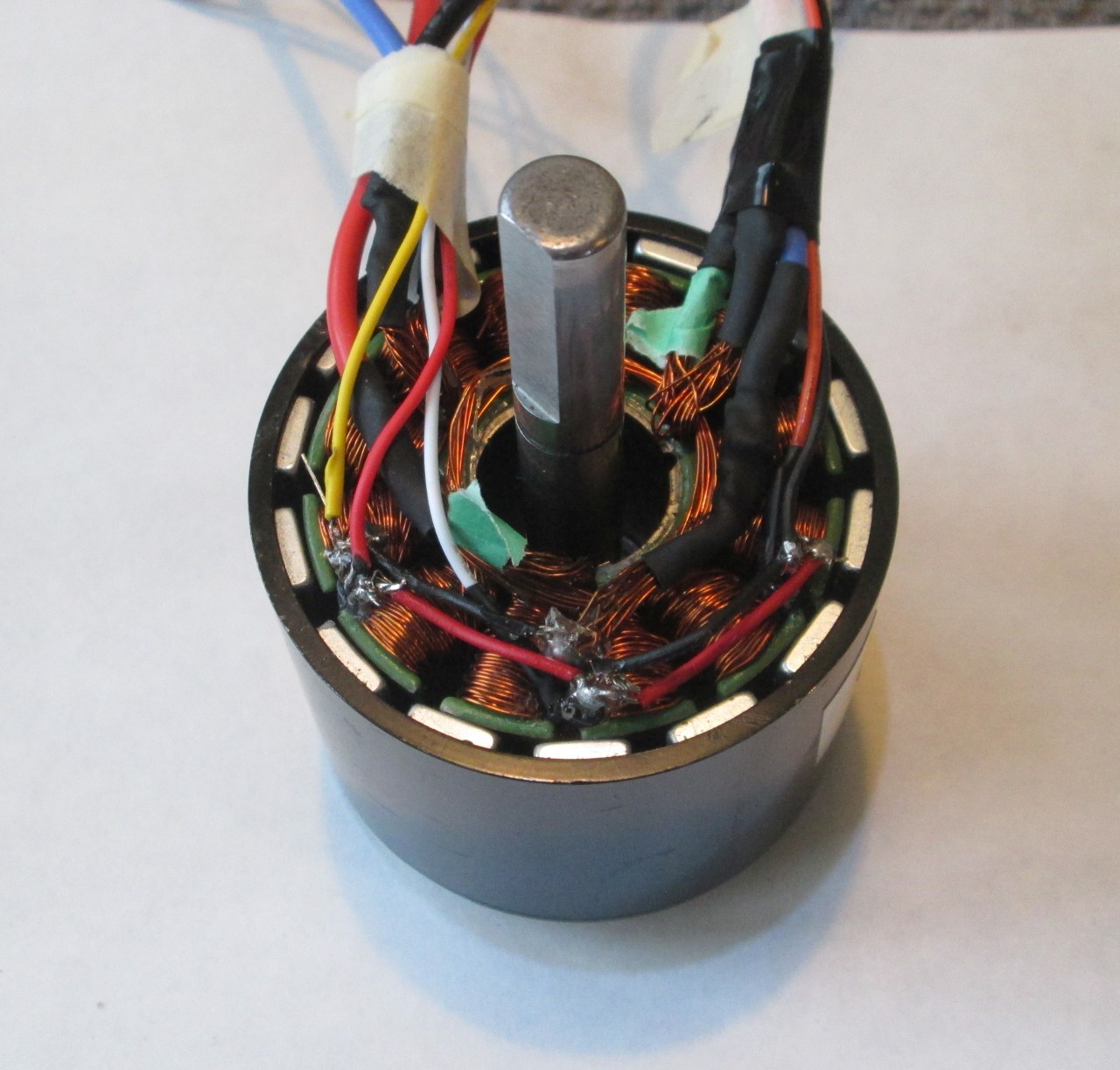
Tracing the windings is the next step. You do this by physically following where the wires go. At first the winding pattern made no sense. This motor uses a 12 winding 14 pole arrangement that’s not as easy to trace. Most motors wind all the poles the same way. This kind of motor winds some clockwise and other counterclockwise. There are three pole-pairs consisting of four windings. Each phase has two opposite polarity windings on one side of the motor, with a complimentary pair on the other.

An unusual pattern to be sure, but it would appear to be somewhat common. Apparently it’s known as “DLRK Evolution”.
Sourced from here: https://hobbyking.com/en_us/blog/rewind-brushless-motors/?___store=nl_nl
Don’t expect me to explain why this particular winding pattern is used. I’m afraid my knowledge ends well before that point. Once I figured the trick out, it was trivial to figure the rest out. Phew. I’ll take all the easy wins I can get today.
Rewire And Repair
Rewiring the phases is straightforward, if not pleasant. I separated the blue wire windings first since they’re already halfway there. Once those wires were fully separated, I just picked another wire at random. Each individual strand is pulled for this junction. A continuity test between each strand and the former blue wire windings separates the phases. Then I moved onto the third pair using the same method.
It took me quite a while to figure out the correct way to wire the phases. If they aren’t done properly, the motor doesn’t work. As such I decided to make the junctions external so I could modify them later. I am not opening this motor again if I can avoid it!

I have no idea why the blue windings are easily separated like this. Makes my job easier, so I won’t complain.

This frankenmotor is the result of several hours of soldering, desoldering, testing, researching, and swearing. I never got it working as shown.

I put the motor down for the day, and I’m glad I did. The next morning I realized I could just break out the winding ends individually for later experimentation. Green and yellow heatshrink bands indicate the winding start/end. That’s critical information to get the motor working again, so don’t forget it!
Repairing the sensors comes next. I happen to have very similar Hall effect sensors in my parts collection. They aren’t identical, but they seem to be close enough. Damage to the sensor board itself was pretty minimal. All I had to do was remove the wreckage from the PCB then slot the new sensors in. In the event I mange to botch this, it’s possible to dead-bug the sensors directly onto the motor.
Which is good, because I manged to botch it. More bad luck.


On the left: how it should have been. On the right: what actually happened. I swear I didn’t push it that hard!

Sensors are snugly fitted into the space between the windings where the original sensor board was mounted. Superglue holds everything in place. Not the first time I deadbugged something on this project. Will it be the last?
When I added the sensors, I did not understand that switching from delta to wye also changes the optimal position of the sensors. There’s a 30 degree phase shift between the two windings which in turn shifts the commutation plane by 30 degrees. Notably I can’t seem to find information on which way the phase rotates!
The good news is the motor will still probably run. Just at lower efficiency. Also, it will probably work better in one direction. I might be able to live with that.
If I can’t live with that, I suppose I can pull the sensors out and replace them. Again. Ugh.
Reassembly
Putting the motor back together is thankfully much easier than taking it apart. All the things that worked against you are now mostly working for you. Just be careful not to let things go at the wrong time and get your fingers crushed by those powerful magnets.
First reseat the front bearing. It’ll probably pop out at some point even if you don’t try to remove it directly. Word of warning, motors are very picky about bearing alignment! The assembled motor should spin freely without any sticky points. A few gentle taps around the bearing perimeter are usually enough to fix that.
I made the mistake of putting the rotor on top of the windings first. In the end, it didn’t make a big difference, though putting the end plate on first is definitely easier. You’ll need to push the windings in far enough that they sit roughly flush with the rotor. This is easily done by putting the shaft through a hole and giving the rotor a good thump.
Putting the end plate back on is slightly harder with the rotor already fitted. Going the other way is definitely the intended order. That front bearing will pop out if you aren’t careful. Thankfully the same trick with putting the shaft through a hole works to keep the bearing in place. A couple of gentle taps got the bearing properly aligned once I’d bottomed out the end plate.


Word of warning: make sure you don’t crush, short out, or pull off any of the wires during the reassembly process. I did a little superglue art to keep everything in the right place before closing the motor up for good. Had I put the end plate on before the rotor I would have had more space to ensure the wires didn’t get damaged.
Preliminary Testing
Because this is the first time I’ve done open motor surgery, I have zero confidence that I will do it correctly. Rather than blow out yet another driver board, I chose to do a test before completely closing up the motor. In the event it doesn’t work, I can quickly swap things around. That’s a good thing, because those connections were not as obvious as I hoped it would be.
I did my initial tests with an oscilloscope. This revealed confusing and conflicting information. Neither the phase angle nor phase voltages made sense. Turns out my initial assumption about how the phases were connected was simply wrong. Delta motors have each adjacent coil connected start to end. Wye motors have all of one end connected together; the other ends are free. All the coils must be in phase for a wye, which kept tripping me up- I was trying to re-use one of the existing junctions which you simply can’t do.

It took a long time to find the correct information, but there was no diagram to go with it. Here’s my own take. Note how each pair has one “head” and one “tail” of the adjacent windings.
To get a wye wound motor, connect ABC or abc together, then use the free ends of each winding as the drive input.
To get a delta wound motor, connect Ab, Ca, and Bc individually. Use each junction as a drive input.
After fully separating the windings, I can make the connections outside the BLDC motor. Better, I can rewire them “on-the-fly” so I can compare a delta winding against a wye winding on the same motor! But, this article is long enough already. Characterizing the motor will have to come later. There are still a few loose ends to tie up in my test setup anyways. For now, suffice it to say I’ve got experimental data confirming the difference in Kv.

A sneak peak at what’s coming next.
Finishing Up
BLDC motors are something I’ve been dealing with for a while now. There’s a lot of nuance there that can’t be explained in a textbook. Information is incomplete and scattered; I had to piece together a bunch of disparate sources just to get this far. Hopefully I can fill in some gaps in your knowledge. At the very least I have now learned some important lessons in how not to modify a motor!
My main intended application for this particular motor is an electric bicycle. A fairly demanding role that requires a high torque to speed ratio. Even using an unrealistically extreme mechanical transmission, the delta wound motor just can’t cut it. I do not need a bicycle that has a top speed of 63Km/H, thank you very much. Legally you’re constrained to about 32Km/H, which is still way too fast. Switching that same motor to wye wound doubles the effective power at the low speeds a bicycle travels at. I don’t know if I would have been able to use the delta motor as-is since it was so underpowered.
Switching between delta and wye isn’t the only thing you can do to a BLDC motor. You can always remove the existing windings and replace them with your own. By replacing the windings you can better tune the motor to match your application. Magnet wire isn’t that expensive in the grand scheme of things. Certainly cheaper than buying a new motor in many circumstances. Perhaps I’ll delve into the intricacies of that later on.
An intriguing possibility that could have significant potential, is the ability to switch from wye to delta while running. This isn’t trivial- switching live high power circuits never is- but it allows for a “virtual” gearbox. Wye-delta starters are used in large AC motors to combine the higher starting torque of the wye with the higher running speed of a delta. I don’t know how much of that transfers over to BLDC motors, but my calculation spreadsheet tells me this is potentially worth investigating. All it takes is a single 3PDT switch.
Summer rapidly approaches- not that we really had winter this year- and that means certain outdoors projects are now viable. I have a few bicycle related projects that will have to be done sooner rather than later. Those are now my short-term priority.
My next step is to run a full power test in a controlled environment. Assuming my not-very-good inverter can handle the load without burning out again, I’ll be clear to mount the motor to my bicycle and do some practical road tests. Either way, it looks like I’m going to have to do a final redesign of my inverter before I can call this project done.
Have a question? Comment? Insight? Post below!