Building My Own Modular Breadboard Development System On The Cheap
Breadboards. We love them. We hate them. We hate to love them, and love to hate them. Despite the fact that electronics continue to get smaller, denser, and less breadboard-friendly every day, the humble solderless breadboard is still going strong. It’s the go-to development system for electronics since 1971, and there’s no end in sight. I use them all the time, even for things you “can’t do on a breadboard”.
While handy, breadboards do have quite a few downsides to them. You can’t shove just any old component into them, they tend to be fragile to handle, and they usually don’t have their own power supply. Workarounds exist, but I’ve never been happy with them. Professional development kits exist, but they seem overpriced and under-performing. Plug in adapters for various parts exist, but they require breadboard space to use. They frequently get pulled out anyways.
What’s needed is a way to completely remove those adapters from the breadboard. Ideally in a way that doesn’t leave them hanging around on the ends of long, fragile wires. While we’re at it, we should make it so everything is rigidly connected together as one unit. An expandable unit, to which more can be added. Oh, this needs to be done dirt cheap, did I mention that? Quite the set of requirements I’m collecting here.
The solution turned out to be quite simple in the end. By encapsulating commonly used parts in modular blocks, and fitting those blocks to a common base, you can get the best features of breadboards without getting tangled up in the worst “features” of breadboards. I haven’t solved every problem the breadboard has, but I definitely solved the big ones I keep running into.
Modular Breadboard Development System
There exist professional breadboard systems that do much of what I’m doing here. Like most existing solutions, I’m disinclined to use them due to cost. You can spend hundreds of bucks to get what is effectively twenty bucks worth of stuff. They all fail at least one of my selection criteria.
This isn’t the first time I’ve tried to build something like this. Far from it. Previous attempts were overly chunky, lacked standardization, and ultimately proved to be impractical to use.

When I started experimenting with modular breadboard stuff, I didn’t have a particularly good idea of what to do. These bases technically do their job in that they keep things from being too fragile; otherwise they’re a real pain to use.
Having learned some important lessons from these partial failures, I’d like to put together my own system that can be optimized for my own specific needs. A few design goals:
- Cheap- I don’t want to buy any new stuff. Not when I have plenty of existing stuff that I can use instead.
- Modular- Oftentimes I want to use parts for more than one project. There should be a way to slot them into the system when needed, and remove them when they aren’t.
- Expandable- Sometimes you just have to spill onto another breadboard. Adding another breadboard (or two, or three) should be quick and easy. Same for any other parts.
- Flexible- Many parts are breadboard unfriendly for one reason or another. There should be a way to use these parts with breadboards without any fuss.
- Sturdy- I cannot tell you just how many times I’ve pulled circuits apart because I moved wrong, or a probe fell off the edge of the table, or something like that. When I put a circuit together I want it to stay together.
What I came up with was a solid base plate that circuit modules plug into. A pin-and-socket system keeps things solidly connected. Modules are mechanically simple- therefore cheap and easy to make. Being simple platforms anything can be mounted to them. It’s so simple I’m actually kind of surprised I haven’t run across something similar before. Perhaps I’m just not good at finding that kind of stuff.
Base Plate
All the modules plug into a base plate. This is, for all intents and purposes, glorified pegboard. If you really wanted to, you could use actual pegboard. I recommend against that because pegboard is usually not that strong. If you can get some nice, chunky pegboard by all means use it!
I decided to use holes laid out on a 2″ grid. A 1″ grid would also work, but I can’t really be bothered to drill that many holes. Modules get mounted using some 5/16″ joinery dowels I happen to have. Other pin diameters would work just fine.

Not much to say here, except make sure those holes are drilled accurately. Even a tiny fraction of error will cause alignment problems. You can probably spot a few holes that are damaged by forcing misaligned pins in.
The base plate can be any size or shape, but a rectangular layout is the most practical. I decided to use a 12″ square plate. That should be big enough to hold a few breadboards and some other modules.
Word of advice: accuracy is key here. Even a few millimeters of drift will cause all kinds of headaches. Use a drill press with a stiff bit to drill the holes, and make sure to do the layout as accurately as possible.
Development Modules
This design revolves entirely around modular development accessories. These consist of things like power supplies, connectors, displays, and the like. Anything goes, and I’ll build them as-needed. Each platform is custom made, though multiple accessories can use the same basic footprint. This means you can manufacture “blank” modules in bulk so you always have one when you need it.
My end decision was to standardize sizes on multiples of 1″. Under that restriction, the smallest practical module is 2×4″. 2×2″ would also be valid, if you’re willing to live with just one mounting pin. Modules are allowed to hang 1″ off the edge; I have ideas for modules that need to be able to do this. I cut several blank module sizes out of scrap plywood:

Three modules of various sizes. That little circular cutout isn’t important; it’s just a side effect of recycling plywood scraps.
Modules have pins in the bottom that mate with holes on the base. Friction fit is preferred, but bolt through is allowed for larger/more permanent modules. I chose to only use two pins per module. You can almost always fit two pins, but three or more requires a degree of precision I simply couldn’t achieve.
A Few Example Modules
The first module conceived was, of course, a breadboard. I went back and forth on exactly how much breadboard I wanted, what would reasonably fit, and how certain sizes would play with other modules. In the end, I settled on two 800 contact breadboards with three power rails. They measure almost exactly 4″ across. In the other dimension I rounded up to 8″.
A word of caution: breadboards don’t always fit the same footprint. I have several “models” of breadboard that are noticeably different sizes even though they all have the same design. Fit the module base to the breadboard, not the other way around. Once I proved the basic concept was sound, I started building more specialized modules.

By far the simplest module in concept, but it took the longest to develop. I had more elaborate plans for things like power connectors. Overall I feel keeping things simple was the right call.

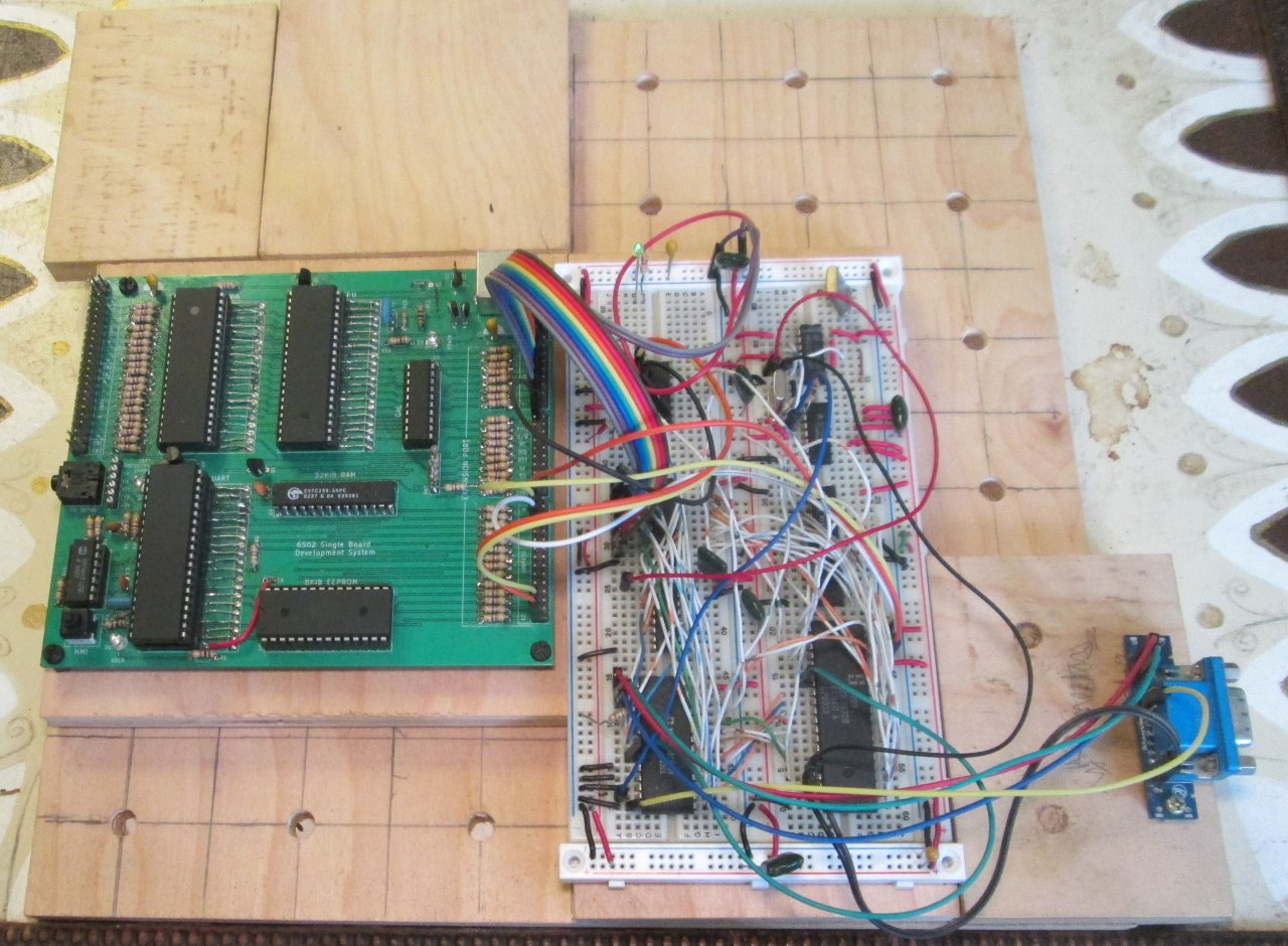
An example of a breadboard unfriendly connector; the DB15HD used in my VGA projects. Real nasty thing that always wiggles it’s way out of a breadboard. Using jumpers to connect to the rest of the circuit has little impact on image quality.

Part of my desire to get this done now was the 6502 SBDS. Lots of wires that could get easily pulled during testing. I can now say farewell to wires getting pulled every time I so much as glance at the SBDS.

Here the three modules are put together into a complete circuit. Also note two blank modules ready for future expansion.
These three modules are the beginning but not the end. I can slap new modules together very quickly, so when I need them I build them. So long as something can be mounted on a small chunk of plywood, there’s no real limit to what can be done.
Finishing Up
Making a modular breadboarding development system has been kicking around my head for about two decades. I made a few token attempts, but lacked the initiative or materials to make much progress. That changed with the SBDS, which is very fragile. My experiments with the SN76489 convinced me to invest in a more permanent prototyping system.
Modular accessories turns out to be the missing link to pull everything together. It solves most of the issues with my previous attempts, allows for future expansion, and modules can be used independently without the base plate or the breadboards. All in all, a very elegant solution to the problem.
The only big thing missing from this system is a clean, easy way to connect the various modules to common power rails. I had ideas for banana plugs, strip contacts, and header pins. None were good enough. Overall, I feel trying to make a common power grid is far more trouble than it’s worth. Keeping things ad-hoc is working fine for the time being. A power supply is a definite future module.
While the three modules I currently have cover most of what I need, there’s plenty of things I want to add: displays, potentiometers, meters, switches, external connectors, batteries, breakout boards, power transistors, relays- the list goes on and on. Building a new module only takes a few minutes. Given the sheer quantity of plywood scraps banging around my basement, they’re also effectively free.
My base plate is a nice size at 12″ square- a sweet spot between “big enough to be useful” and “small enough to fit on a desk”. Thinking long term, I’ll probably build another base plate eventually. A slightly wider size (e.g. 12×16″) would be more flexible while still being desk friendly. Conversely, a smaller size (e.g. 8×8″) would be useful for small projects that only use one or two modules.
Prototyping electronics is sometimes pretty tricky. Not only do you have to connect everything together electrically, you oftentimes need to figure out how to connect them mechanically. For breadboards this is even worse, since you’ve got to come up with ad-hoc adapters that usually refuse to stay put. My modular breadboarding system keeps everything together in a mechanically sound unit. So much time wasted in the former, while the latter took a day to design and build.
August is over, which means a lot of things are going to happen very quickly. I’ve got multiple projects I’m plugging away at, in various states of completion. One of those projects is a long overdue refresh of SDR. I have some ideas for cleaning things up to make this site more usable. That won’t necessarily be the next thing to happen, but I’d like to get that done before the end of the year. Until then, I’ll keep on keeping on.
Have a question? Comment? Insight? Post below!