Measure Mechanical Power Using A Self-Built Prony Brake Dynamometer
One of the most common things you need to do as an engineer is measure the power of something. Happens all the time. For example, I just got done laboriously rewiring a BLDC motor to try squeezing out more power. Right now I don’t really have a good way of actually measuring that power difference. So I don’t really know if it’s truly better or not. Getting those measurements requires special equipment.
Motors cross the electrical/mechanical divide and must be analyzed as both types of machines. Measuring electrical power is easy, particularly with a DC machine. Just multiply volts by amps. You can measure both using readily available tools. Being an electrical engineer, I have plenty of such tools and know how to use them. No problem!
Mechanical power measurement is more niche. Tools to do so are available (they’re called dynamometers), but they aren’t common. Nor do dynamometers tend to be cheap. No way you’ll get your hands on decent equipment. Well, the good news is that as long as you don’t push things too far, it’s easy to make your own. All you need is some scrap wood, three bolts, a weighing scale, and a cheap tachometer. Adding a proper base only requires a handful more materials.
Since the proper tools are far too hard to get, building your own dynamometer is the only viable way to experiment with motors. I’ve been meaning to do this for a while now, and I’m glad I got off my ass and just got it done. Anyone who works with small motors is going to want to build a small dynamometer ASAP!
Measuring Motor Power
Mechanical power is defined as work over time. Work is a bit of catch-all phrase that typically means applied force multiplied by distance traveled. Power is therefore represented by this equation:

Rotating systems (e.g. most motors) use the same basic equation adapted to the situation. Torque is used instead of linear force; rotation speed covers both time and distance. In a rotating system, the power equation ends up looking like this:

So, to get the power output of any motor you multiply the shaft speed by the applied torque. Obviously this hinges on getting accurate values for both measured quantities.
Measuring shaft speed is relatively easy. If the shaft is slow enough you can just eyeball it. Counting video frames is another fairly reliable way. Beyond that you use a proper tachometer of some sort. Tachometers aren’t common equipment per se, but they’re reasonably easy to get. Building one is surprisingly practical too.
Torque is the hard part. Professional dynamometers use strain gauges to measure torque directly. Strain gauges are not easy to get your hands on. They’re specialist equipment that requires special circuitry to get any results. There’s a simpler low-tech way: use a lever arm clamped to the motor shaft. Torque is lever length multiplied by linear force, so you can measure it using an ordinary weighing scale. In a pinch you can even use weights.
To fully characterize the motor, you also need to apply a load. This can be done by connecting to known mechanical loads like a fan. Using static loads isn’t ideal though. What you really want is the mechanical equivalent of a variable current load. Typically this is a friction brake that can be precisely adjusted. Checking the power of a motor under various loads lets you characterize it- exactly the same as you might characterize an electric power supply with a test load.
To summarize: if you want to calculate motor power you need to measure the speed and torque. To fully characterize the motor you also need to apply a controlled, variable load to it. Using very simple means we can simultaneously load the motor and measure the toque.
Prony Brake Dynamometer
By far the simplest dynamometer you can build is the Prony brake. This consists of a friction brake attached to the motor shaft. Torque is measured by a lever arm connected to a counter-force; usually a spring balance. Prony brakes are easy to adapt to available resources, so you can make one quickly out of stuff you probably already have.

Schematics for a Prony brake. Dimensions taken off my own brake design. Measurements are approximate, and the brake itself can be built in more or less arbitrary sizes.
To make the arms, cut a plank of wood to double the thickness of one arm. Exact dimensions aren’t critical. Make sure you have enough room to put three transverse bolts through the arms; two around the motor shaft and one at the far end. Put the far bolt at a known distance from the shaft. This measurement isn’t critical, but you’ll need it for calculations, so try to make it something mathematically convenient.
After drilling the bolt holes, cut the plank down the center to get two matched arms. If you did a good job you’ll be able to flip one arm around and bolt them together flat. I didn’t do a good job myself, so I just cut down the bottom arm. It’ll still work fine that way. While bolted together flat, drill the shaft hole. Make it a close fit on your shaft- 1/2″ is a good all-around choice.

My actual brake, after cutting and drilling. I think this wood is oak. Try to use the densest, hardest wood you can get.

My actual brake, after trimming down the bottom arm. I can no longer do symmetrical measurements, but that isn’t a big loss.
Under some conditions, the brake arms alone might be enough. If your arms are fitted to the motor shaft, and the motor is securely mounted to some structure, you can just slap the arms on directly. Otherwise it’s a good idea to make a base. This holds everything together rigidly, so that there’s a common reference point to measure from.
I added a dedicated shaft mounted in bearing blocks to minimize the amount of setup required when swapping motors around. Space is always a concern, so I trimmed it down as far as practical.

A compact, practical design. My bearing blocks stack, so I can adjust the vertical height relatively easily.
I 3D printed some simple plain bearing blocks to support the shaft. These won’t be too heavily loaded so plastic ought to be fine. I took the bearings from Scribble’s new carriage and added a mounting flange. Proper “pillow block” bearings are relatively easy to get otherwise. If all else fails, a hole drilled through some scrap wood can do in a pinch.
Using The Simple Dynamometer
Building the brake isn’t terribly interesting, nor is the resulting product obvious in it’s use. I want to get measurements from my BLDC motor, so I’ll explain the basics of how to set things up and use the dynamometer.
For the background on my particular motor, I did a whole article explaining how and why I rewired it. Long read made short: delta wound motors have high speed low torque, wye wound motors have high torque low speed, and I want to know which configuration is better for my projects. I know it’s wye wound, but I want the quantitative evidence to back it up.
Preparation
A complete dynamometer has two additional components: a tachometer and a scale. My tachometer is a cheap one you can get pretty much everywhere. 20USD is plenty enough budget. Just make sure it can handle your expected motor speeds. 10,000 RPM is more than enough for most applications; 100,000 RPM will cover pretty much everything else. Very slow speeds are better handled counting revolutions with a stopwatch.

I strongly suggest using a non-contact tachometer, but they all seem to be non-contact these days. This was an Amazon purchase, but Harbor Freight sells an effectively identical one.
As for the scale, you want one that can take a reasonable amount of force. Something like 5Kg with 1g resolution or less. An ordinary kitchen weighing scale will do fine. Luggage scales also work well, but you’ll have to build a stand to hang them off of. In that case the arm should be arranged to pull, not push.

Examples of a push type scale and some pull type scales. Push scales tend to be easier to work with. I’m using the push scale which came from Harbor Freight 20 years ago. I assume they still sell literally the exact same one.
Experimentation
Connect the motor to the dynamometer apparatus. Don’t power it up just yet. Make sure that everything is connected rigidly, and that the shaft spins freely. Loosen up the brake until this happens. You may need to build a dedicated test jig to keep everything aligned.

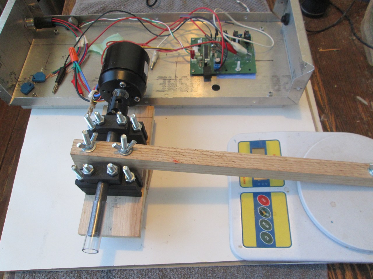
Coupling the shafts together can be done many ways. My 3D printed coupler worked okay (despite being only half printed!), but using a rubber hose with a couple of hose clamps also works just fine at low powers. The motor bracket is physically screwed into the dynamometer base so it can’t rotate.

This experimental test setup is quite scruffy, but reasonably effective. Were I not forced to use the aluminum casing as a heatsink, it’d be significantly smaller. Oh well, it got the job done and my kitchen table has since been reclaimed.
Set up the torque arm on the scale. Try to make the contact point as close to 90 degrees as possible- the arm should be horizontal. Tare out the weight of the arm. If you can’t tare the scale, record the arm weight so you can subtract it during your calculations. Adjust the brake until it just grips the motor shaft.
Power up the motor to a low speed. Make sure the motor is spinning such that the torque arm is registering on the scale. If the motor is spinning the wrong way, either reverse it or flip the dynamometer around. Once things are stabilized record the speed and torque. Feel free to record any other useful data, e.g. fuel consumption, power supply current, throttle position.
Increase the brake force by tightening the brake. Record the new data. Repeat for whatever combinations of speed, torque, power, brake force, or other points of interest you’re interested in. Noteworthy data points include the no-load speed and stall torque. Just be careful not to overload the motor to the point where it gets damaged. I’d suggest having a way to shut things down quickly in case things get out of hand.
Calculation
Once you’ve gathered all the data, you can start calculating with it. This is reasonably straightforward, but you’ll have to keep the units consistent. Torque is typically measured in newton-meters or foot pounds. Speed is pretty universally measured as RPM. Pick whatever units you need; they’re all pretty easy to work with. For both these equations, T is torque in your units of choice while N is speed in RPM.
To get an output in watts using kilograms, you need to convert RPM to radians/sec, and kilograms into newtons. Both are rolled into this equation:

To get an output in horsepower using foot-pounds, you can simply use this equation:

Don’t ask me where the magic 5252 constant comes from; I can’t be bothered to chase down the esoteric conversion constants for units I never use. Handy that it’s so memorable though!
After picking the appropriate equation, you can calculate the power for each data point. Analyze them however you will. For my example, I chose to record the power and torque generated by my BLDC motor from no-load to stall under two different winding schemes.


Wye configuration is strong on the torque, as expected. Power peaks around 1100RPM, though I found it difficult to get good readings near the extremes.


Delta configuration is pretty poor across the board. While maximum speed was significantly higher, I found it almost impossible to load the motor above 1000RPM. I suspect the true power peak is around 1500RPM but my test setup can’t effectively measure it.
If you’re curious, I put together a spreadsheet with my data. This automatically performs the calculations, eliminating potential errors. I got similar results using the spreadsheet as I did manually running the calculation. A disadvantage to manual calculation is that you need to juggle multiple unit conversions even when using SI units.
My experimental data spreadsheet is available here if you want to see the actual data points:
Testing went pretty smoothly with no unexpected explosions. Always a nice result! My main problem ended up being adjusting the brake. I had to file down the bearing surface a little bit to give it enough “bite” to stall the motor. Small adjustments on the wingnuts had large effects on the motor. I tried to get a similar range of test values, but it’s tough to be precise. A way to improve the sensitivity of the brake is on my to-do list.
Oddities in the curves are mostly explained by the limitations of my equipment. I can’t get particularly precise results with a Harbor Freight tachometer/scale combo. I wasn’t looking for particularly precise results, so I don’t care too much. Compared to precalculated values, the experimental values held up well. I am a bit surprised with how poorly the delta configuration fared, though I suspect it ought to have a peak power of about 8 watts around 1500 RPM. The much reduced torque made getting those readings impossible. Perhaps I might try again with a better brake.
All these tests were done with my bench supply, which can only supply around 30 watts total. This was by far the biggest limiting factor. Electrical power was the full 2A at about 15V for even moderate loads. Current is the bottleneck; my motor has a very low winding resistance. Even moderate loads kept the power supply in constant current mode. Wye configuration fared better under these circumstances, as expected.
Finishing Up
I’ve been kicking around the idea of building a dynamometer for a while now. Motors are pretty much impossible to characterize objectively without one. Rewiring my BLDC motor was the big kick that got me moving. I really need to characterize the difference, as well as the efficiency of my controller. All the theoretical calculations in the world won’t do anything without experimental evidence to back them up.
A word of warning for zealous experimenters: the wooden arms will eventually catch fire at high loads. How high? I don’t know, nor do I (intentionally) want to find out. Lubrication helps, though not as much as you might expect. I’d suggest keeping things to short tests of a few dozen watts maximum. Larger loads require more sophisticated brake designs with integrated cooling. Not impossible to build, but certainly not simple.
Just as important as characterizing the motor, is characterizing the inverter. My efficiency equations are… not looking good. But like I said, theoretical calculations are meaningless without experimental evidence. By putting a known load on the motor I can get some objective numbers on things like converter loss or thermal dissipation. This idea holds true for other systems too; e.g. measuring losses in a mechanical transmission.
While I’m clearly interested in electrical motors, dynamometers work perfectly well with any motor. As long as it turns a shaft, you can measure it with a dynamometer. Linear motors can be analyzed by just applying the work equation directly. I’m not entirely sure “linear dynamometers” exist as such. It wouldn’t be too hard to adapt the basic concept to a linear system if the need ever arises.
Dynamometers can be significantly more complex. I have elaborate plans for a fully automated dynamometer that can both automatically test an attached load, and power said load by itself. Such a dynamometer can not only characterize power producers, like motors and engines, but can also characterize power consumers. This is roughly equivalent to a four quadrant electrical power supply. When will I get around to that project? Who knows!
I’ve been wanting to build a dynamometer for a few years now. It’s one of those tools you don’t need, until suddenly you do. Getting objective measurements of my BLDC motor was what pushed the dynamometer from “nice to have” into “need to have”. Always nice when you can design around real measurable numbers instead of gut feelings.
Summer 2024 has proven to be… less than ideal for building things. All us Americans are a little frazzled right now given the SCOTUS presidential immunity ruling and Project 2025. I’ve been stretched a little bit thin here; what with juggling a job, this blog, various housekeeping tasks, my transition, and being more involved in politics. I have a few other projects that are mostly complete but everything else seems to be taking priority for now.
Have a question? Comment? Insight? Post below!