Building a Constant Current Load for Power Supply Testing.
Usually when we talk about “power” we refer to a power source, e.g. “battery power”, “mains power”, etc. Sometimes though, its more useful to refer to what’s using the power: the load. Having a controllable load is particularly useful when designing a power source.
You can, of course, buy professional quality equipment to do this job. Lacking the budget for that, there’s no real shortage of “just a PCB” loads on pretty much every online marketplace. However the basic circuit is so simple, and requires such common parts, you can probably throw one together with stuff you already have lying around.
So really, why not build one?
Operational Theory
A constant current load is pretty simple. It’s effectively the inverse of a constant-current power supply. The difference is a power supply contains an internal source that it couples to an external load; constant-current loads have an internal load that couples to an external source. It really is just a matter of perspective here- the control circuit is almost identical between the two.
I suppose it would be a good idea to explain how that control circuit works. Lets ignore the annoying real-world problems that might crop up for now. Just consider an ideal op-amp connected as a voltage follower. Any voltage on the input is faithfully replicated at the output.

Add a single resistor between the output and ground. Ohm’s Law tells us that current in this resistor is proportional to the voltage divided by the resistance. Ergo, current in the resistor is directly related to the input voltage.

Real op-amps have feeble output current. To get more than a few milliamps, we have to amplify that output current with a transistor. Now the output current is boosted by the transistor- but the op-amp still takes its feedback from the resistor, so the loop is still closed. Input voltage still controls the resistor current.

With that added transistor, we are no longer limited to using the op-amp’s power supply. By connecting the transistor to an external supply, the input voltage can control the current in a completely different circuit. The only thing that matters is this current flows through the sense resistor. This is the fundamental basis of Simple Load and all the other constant current loads you’ll find.

It’s easy to convert this into a constant current power supply. Just put the adjustable load in series with the fixed load and an external source. Converting the power supply to a load is just as easy. Put a constant impedance across the output; use the power input as the load terminals.
Building Simple Load
Since it is quite simple, building Simple Load should be nice and quick. Let’s just say it took a lot longer than I really wanted it to. At least it’s only late until it’s done.
All my design calculations revolve around a maximum of 30V/3A. This might be pushing things a bit too far. So far Simple Load hasn’t exploded… yet. I haven’t truly tried to push it to the limit either.
Circuit Design
Knowing the theory, we can design a real circuit to act as a constant load. Even considering all those annoying “real world problems” we loudly ignored in the theory section, this is still a remarkably simple circuit:

On the right hand side is the constant current load itself. You’ll notice it is almost identical to the idealized version with three extra components. That 100R resistor counteracts oscillations that can happen when the output is switched rapidly. Anything between 100R-1K ought to work.
The extra resistor/capacitor labeled “COMP” are compensation components used to prevent the op-amp from oscillating. I’ll confess right now and say I have never, ever had this circuit misbehave. As such, I have never actually had to add compensation.
I suspect this is because the LM358 is a low end op-amp with terrible frequency response (knee at 4KHz). Effectively it already is compensated well enough. If you experiment with higher bandwidth op-amps compensation will likely become necessary. Easier to just assume they are required and provide space for them. It’s tough to patch components in on a finished circuit.
I chose 0.1R for the sense resistor. This imposes a modest burden of 0.3V at maximum current. Not enough to worry about. At peak design current it has to handle about 1W.
MOSFETs are pretty much universally used for these circuits. They have near-infinite current gain, so they are almost ideal. Almost, because finding a power MOSFET that works in the linear region is incredibly tough. Linear power MOSFETs definitely exist, but be prepared to pay mad money for them. Switching MOSFETs can be used if they are sufficiently overrated. Don’t trust the SOA chart in the datasheet because switching MOSFETs aren’t really tested like that. Expect to blow a MOSFET sooner or later. I used an IRF730 (400V, 5.5A) and it’s held up well so far. How long will that last? Who knows!
LM358s come two per package, so I used the other one to amplify the voltage across the load resistor. It’s just 0.1R, so it only provides 0.1V per 1A. I boosted that up by about 10x for the panel meter. Note that’s a 1K1 resistor, not the more common 1K! The ideal resistor ratio is exactly 9:1. In practice it doesn’t really matter too much since the meter is too inaccurate to bother with small errors in the amplifier.
I decided to use a TL431 as a reference. This decouples the control voltage from the power supply voltage. 6K8 in series with a 1K potentiometer allows for a control voltage of 0-3.2V. Close enough.
I chose Adafruit “Mini 3-wire Volt Meters” for the sole reason that they were cheap and they did the job. Crucially they are three-wire meters, so they have separate power supply and sense inputs. Two wire meters won’t work since they combine the two functions. At best they go down to about 2V, which is far too high for this application. In retrospect I really should have splurged for better meters since they only go down to 0.1V. Acceptable for voltage, but limits current resolution to 100mA. Accuracy at the low-end of the scale is also pretty poor.
Power comes from a generic 12V 100mA plug pack I had lying around. 2.1×5.5 connectors seem to be the most common, so I went with that.
Circuit Construction
A proper PCB would be nice. Alas, there will only ever be one Simple Load so there’s no real point. PCBs are fairly expensive and I do have some protoboards I should use up. I chose the Chip Quik SBB1005. It’s about 1.5×2.75″. It doesn’t have mounting holes, which proved a bit finicky.
Tetris-ing all the parts together was a bit of a challenge. I just manged to cram everything together on that tiny protoboard. In retrospect a slightly larger board would have helped a lot.
Oh well, it all came together in the end.

I chose to mount the MOSFET remotely. It turns out TO-220 leads slip quite nicely into 0.1″ header sockets. Due to the way I put the board together this is kind of necessary; the board is oriented such that the MOSFET would be facing the wrong way. Were I intelligent, I would have used a panel mount connector for the plug-pack to fix this problem.
Speaking of those header sockets, I used 0.1″ headers with IDC connectors for all the off-board parts. I standardized on putting the ground on pin 1. All the wires are solid-core 22AWG. I tried to adhere to a color code, but my options are pretty limited. Red is positive, black is ground, and honestly that’s all that matters.
Impressively, there were no soldering errors and everything is mostly straight. Granted, I have seen “professional quality” machine soldered boards where everything was pointing in different directions. You don’t get credit for a circuit that looks good, only one that works.
Case Construction
Electronics cases are expensive, and it’s kind of a given that a professional case is going to be overkill. Instead, I used some scrap materials to make a case.
There are no special requirements for the Simple Load case. It just has to hold everything together. As such I settled on the laziest design I possibly could: a rectangular box. Little forward planning went into it (it’s a box, you don’t need much strategic planning to build a box) so I made minor adjustments on the fly.


Most of the box is made from 1/2″ plywood, simply screwed together at the corners. For the front and back panels I used 1/16″ aluminum sheet. I used some 3/4″ strips to hold down the aluminum panels, which gives a pleasing visual effect.
For a heatsink I simply riveted three U-shaped aluminum panels to the back. I did a bad job forming and mounting them. Despite how crude they look, they do in fact work. They’re a little undersized, but that is less to do with how they look and more to do with how little space I had to work with.
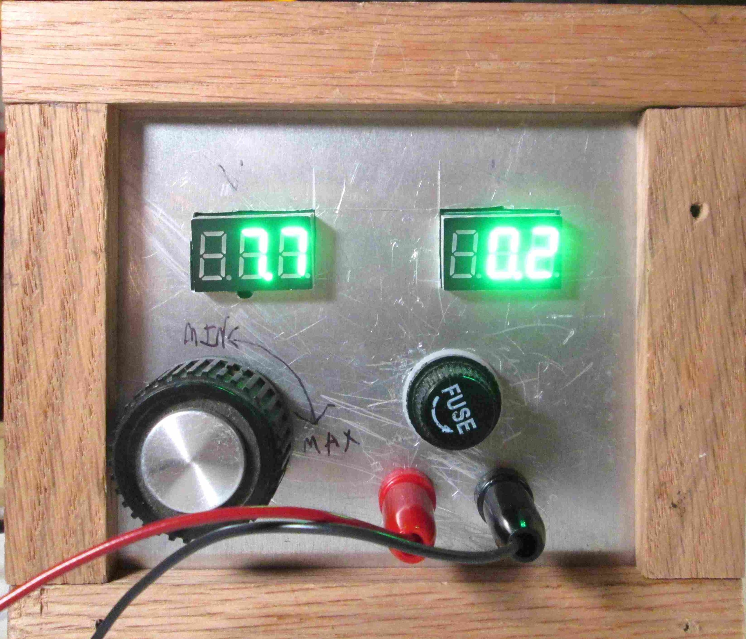
If I had to change one thing, I’d make the case slightly deeper. I have just enough space inside to fit everything, but it is pretty crowded in there:

You’ll notice those meters are literally taped in. I couldn’t find a better way of mounting them, and I plan to replace them sometime. No sense in spending too much time getting them right.
Testing Simple Load
With everything put together it’s time to do the final tests. I already know the circuit works because I’ve been testing it all throughout the design/building process.
My main test goal is to determine the maximum power Simple Load can handle. To do that requires calculating the performance of the heatsink. It’s easier than you’d expect.
All that’s needed is a power supply capable of powering Simple Load up to it’s limit, and a thermometer. Temperature is measured as close to the power transistor as possible. I set Simple Load to a known power, let it sit until it reached equilibrium, then performed the following calculation:
(Ttransistor – Tambient)/Power = Thermal Resistance
Ambient temperature is effectively room temperature, transistor temperature is the temperature of the transistor case, power is simply current times voltage. Thermal resistance will have units of C/W.
To calculate the maximum allowable power, the equation is rearranged thusly:
(Tmax – Tambient)/Thermal Resistance = Power
Ambient temperature for this is usually 50C, which accounts for a poorly ventilated case in close proximity to other heat producing stuff. Maximum temperature is 150C, which is what most power transistors can tolerate. Thermal resistance is what you calculated with the last equation using experimental data. Power is the maximum sustainable load.
I ran the numbers for several power settings and got about 2.8C/W. That’s… not great. 2.8C/W corresponds to a maximum power of just 34W. Theoretically the IRF730 could handle about 100W, assuming the SOA curve isn’t wrong (it probably is). On the plus side, I find it highly unlikely to need more than 34W of capacity.
Finishing Up
Simple load is the first project I’ve completed in a very long time. Sure, it took far longer than I expected. Sure, it’s got some problems I’d like to fix someday.
But you know what? It’s done. I feel pretty confident about letting somebody else use it- or showing it off. Everything has reached that point where you just expect it to work. Any improvements would be marginal- or a radically different project.
I only have one major complaint; those panel meters are simply inadequate for high accuracy measurements. Simple Load is perfectly usable as-is, but to get that extra accuracy I have to plug an external ammeter into it. Replacing the meters isn’t really part of Simple Load though; they don’t change the underlying circuit in any meaningful way.
The only other thing I want to do is clean up the case, give it a proper coat of sealant, and add proper labels. Again, this has nothing to do with the circuitry.
So there’s nothing left to do. It’s time to move on. Specifically, I’d like to move on to the project Simple Load was literally built for.
Have a question? Comment? Insight? Post below!