Finally Getting Around to Fixing my Most Embarrassing Mistake Thus Far
Some time ago, I presented my Multipurpose BLDC Motor Controller. It was, to put it bluntly, a bit of a fiasco. Three prototypes, two of which exploded, and none of them really worked properly. An “educational experience” if you will.
When people say something is an “educational experience” they almost always mean “I learned a lot about how not to do something”. By that metric, my BLDC controller is probably the most educational thing I have ever done. The only good news is that I do in fact learn (eventually), so by the third prototype I had things mostly figured out.
Of course, the more mistakes you learn to avoid, the more egregious the ones you make become. It was only a little oversight, but I ended up in the worst place a project can be: almost working. My motor runs, but it can’t start itself. Yay.
At least when the first two prototypes exploded, I instantly knew that they were dead-ends.
The good news here is that the problem is fairly easily fixed. I only need three new parts and a few minutes. Something that could have been done during the months of design work, but let’s dispose of that thinking for now.
A Recap of the Problem
Pretty much every motor controller uses transistor switches to control current to the motor. To allow for forward/reverse/neutral/brake functionality, there needs to be at least two transistors per winding.

We call the basic circuit an H-bridge, a description that is perhaps slightly too literal. You may recognize the basic two-transistors in series as a push-pull configuration, usually as the output to an amplifier. In many ways a motor driver is a special type of power amplifier.
My mistake concerns the upper transistors in these push-pull pairs. Remember, to turn a transistor on, the base/gate needs to be positive with respect to the emitter/source. FETs and BJTs follow the same basic rules, so I’ll assume MOSFETs in my explanations from here on out.
As shown, the upper MOSFETs have a floating source. That’s a problem. Unless the source is given a low impedance connection directly to ground, this will cause the source voltage to rise. Gate voltage is not floating, so the voltage between the two decreases. Either the MOSFET stays stuck in it’s linear region, or it simply doesn’t turn on.
Vgs is going to be limited to about 20V maximum, so keeping Vg above Vs is going to have practical limits. Very small practical limits; if Vgs is 10V, then Vs can only rise 10V off ground.
MOSFETs have Vt, the threshold voltage. If Vgs goes below Vt, the MOSFET turns off.
Thanks to complicated semiconductor physics (that I’m not explaining here), you can put Vt pretty much anywhere on the IV curve. Vt can even be negative!
Your average power MOSFET has a typical Vt around 5V. However, the maximum conductance is reached around 10V.

A more practical solution is to float Vgs, such that the differential voltage remains more or less constant. When you’re demonstrating this idea by slapping down abstract symbols on a schematic, you get the above image. It’s not a terribly partial circuit in itself, but it shows the basic concept that real circuits must achieve.
Complimentary Pairs and Bootstrap Circuits
There are a few solutions to the floating source problem. We could swap the N-FETs for P-FETs. A P-FET is basically “upside down” compared to the N-FET, which means the source is now fixed to the positive rail and the FET turns on when the gate is pulled negative.

A few snags in this solution include finding appropriate P-FETs, logical signal inversion, and the cost of a high-power P-FET. With a new design, you can make that work. Retrofitting P-FETs into an existing design is more or less impossible.
You can still use N-FETs in the circuit if you can make the gate voltage float on top of the source voltage. Many solutions to floating the gate exist, but you’ll usually run across a diode-capacitor circuit similar to this:

This is known as a bootstrap, or more specifically a high-side bootstrap. “Bootstrap” already has a dozen different meanings in electronics; it pays to be overly specific. It’s a variation of the charge pump, a capacitor based DC-DC converter. Pretty much every high side MOSFET driver uses some variant of this circuit because it’s cheap and it does the job.
Bootstrapping only works if the MOSFET is switched regularly. Wait too long and the charge on the capacitor leaks away. Previously I worked with high-side MOSFETs that were guaranteed to be switched. Unfortunately the MC33035 does not switch the high side outputs unless the motor is already turning. That’s why my circuit was able to keep the motor spinning, but couldn’t start it.
Fixing the High Side Drivers
My mistake was in two parts. First I failed to carefully read all of the MC33035 datasheet. There was a reason there was a conspicuous lack of charge pump bootstraps. Second, I failed to check if my gate driver had a “keep-alive” function where it would automatically top up the capacitor. Some drivers do this, but high-side only drivers are very rare, so I only had one real option (the IR2118).
Since I’m more or less locked into using N-FETs with the IR2118, there aren’t a ton of options for fixing up my circuit. I tried a few things here and there, but it’s readily apparent that the only thing that will work is an isolated 12V supply for each phase.
There exist some marvelous little DC-DC converters that do exactly that. They’re surprisingly cheap, too! I chose the Mornsun IF1212S-1WR3. I don’t know exactly how it works, but I suspect it’s a fully isolated version of the simple charge-pump bootstrap.
All I have to do is remove the bootstrap diode then add the DC-DC converters. Simple enough. The only issue is the DC-DC converters are much bigger than I anticipated.

I expected these to be about half the size they are. Don’t know why, I just did.
Well, the good news is I can make them fit. I don’t know if I can use the other two boards like this though. I may be looking at a fourth re-design of an already troubled project. Bah. Cross bridges as you come to them.
Retrofitting the Solution
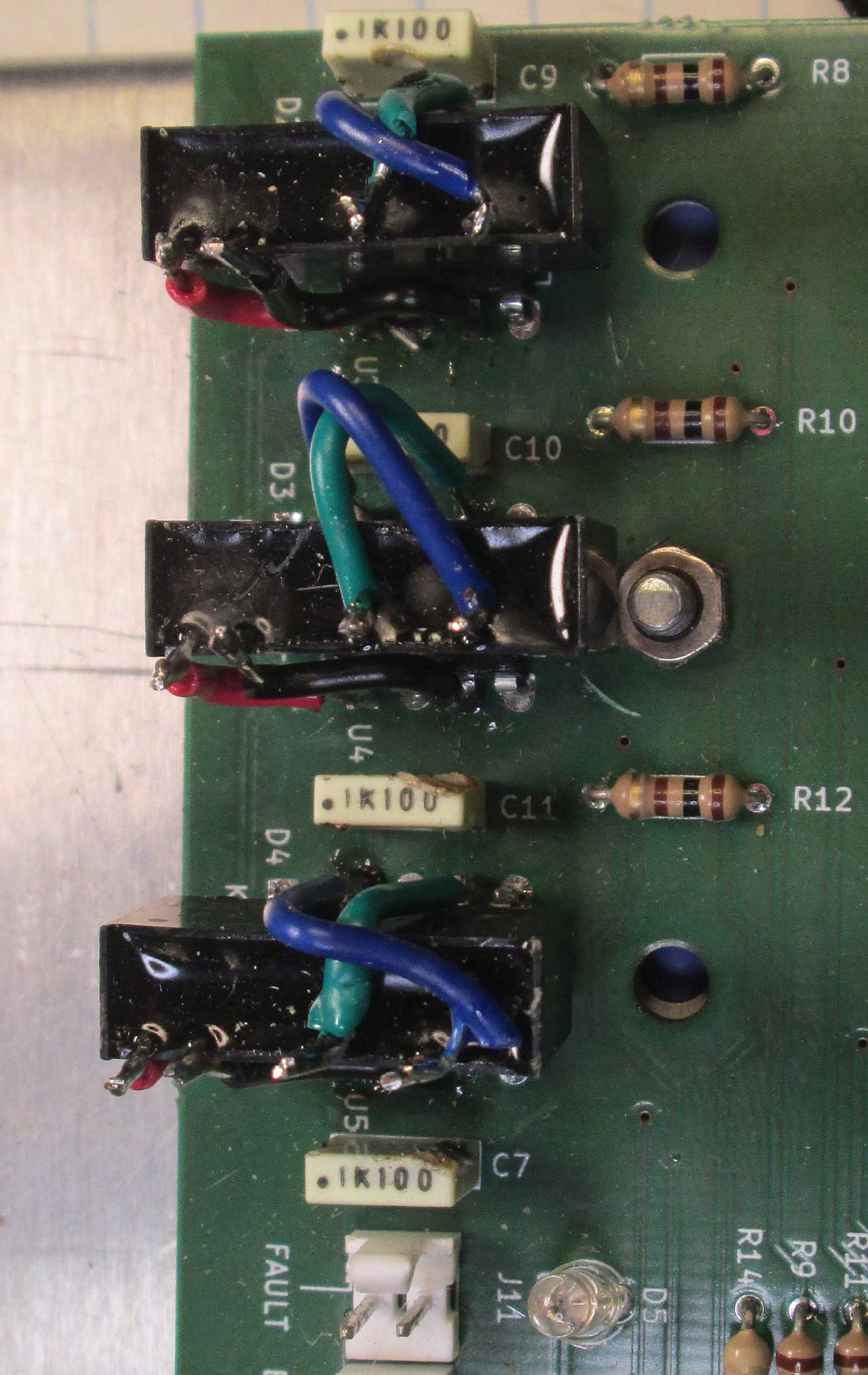
There is no way to put the DC-DC converters directly onto the PCB, so put that out of your mind immediately. We’re going to have to do things a little more freely.
Each DC-DC converter is placed over it’s respective gate driver IC. A little dot of glue keeps them in place.
I removed the now useless diodes. Leaving the diode in probably wouldn’t cause any trouble, but I removed them just in case. Diodes are cheap, so I don’t mind sacrificing a few.
Each DC-DC converter is wired into their gate driver as follows:
- +Vout is connected to pin 8 ( of the IR2118).
- -Vout is wired to pin 6 (Vs).
- +Vin and -Vin are connected to the +12V and GND respectively. (pins 1 and 3, Vcc/COM)
Obviously those tiny leads can’t reach to the connection points by themselves. I added a few color coded jumpers.
A more general form of this is known as dead-bug construction.
It’s popular for high frequency (e.g. RF) circuits where interconnections must be kept short, and high-power circuits where interconnects must be chunky and highly isolated.

Just enough space to fit the DC-DC converters on top of the IR2118 DIPs.

Ugly, with some collateral damage. Soldering in tight locations is tricky!

Much like the 6502 board, I decided printing out critical reference information was a good idea. Doubly so here, what with the history of explosions and all.
Visually this is pretty unappealing. I don’t care because this board will be shoved into a case that will never be casually opened. Make it work, then make it look good is a doctrine all engineers ought to follow.
You might think this process is exceptionally crude. You’d be right. You will however find commercial products fresh from the factory with components hastily patched onto the PCB. When you’re making a few circuits for your own personal use, you can throw away a slightly buggy board and start over. When you’ve put together a few thousand of them that have to be shipped now, you usually don’t have that luxury.
Testing the Fix
Given the already troubled history of this project, you can bet your vital organs that I’m testing the hell out of it. All I have to do is plug it in and see if it starts up.
If it explodes again, at least I can conclusively lay this project to rest. How did it go?
Success!
Well, okay this was actually the third test. At first I was having trouble with the MC33035 getting stuck in fault mode. Eventually I remembered the resistor in the current sense network was too high. Second I didn’t actually record the correct order of connections between the motor and the PCB. Sorting both of them out fixed the problems not related to the high side drivers.
But, the results are undeniable. After three years, three prototypes, and a lot of embarrassment, it works.
Finishing Up
It is a simple fact of life that sometimes the things you do don’t really work out. At some point you have to ask yourself if it’s time to give up or if you ought to stick it out. Contrary to all that worthless life “advice” you’ve doubtless heard, there is no simple answer. You have to judge each problem by it’s own merits.
I spent a lot of time and money on this BLDC board. I don’t have detailed records, but an estimate is somewhere close to 100USD. That probably means nothing due to the global economic implosion, but the point is that it was expensive enough most people couldn’t write it off. Looking around, the value of a prefab BLDC controller is about 30-50USD, so even the first prototype was probably not cheaper than buying the prefab.
Of course part of the reason I did this was because I was unhappy with the prefab solutions. I’m not simply interested in making a motor spin, I wanted something flexible enough to work with multiple potential applications. In particular I need to be able to convert mechanical energy to electrical; I also need all the controls to be broken out so other systems can hook into them. I needed a building block, not a complete house.
All that being said, I may still have to design a fourth BLDC controller. IR2118s are very expensive, and there would appear to be no real alternatives. It may be possible to butcher the board into accepting an alternative, though that would be even cruder than this particular solution. Perhaps there is a happy medium, where I can plug in a customized module into the IR2118 socket. I need to think about it more.
While I would love to write “the end” on the last page of this troubled project in one of those ultra-pretentious script fonts, something tells me this project is going to come back eventually. Because everyone loves unwanted sequels!
Since I only have two projects in mind for this driver board, I may just stick to using this hacked up fix for both. But, if I ever need more of them I’ll have to do the redesign work. I suppose I’ll talk about it when it happens.
On a more sombre note, this will likely be the last thing I publish in 2022. Holidays have an ironic way of using up all your free time.
Have a question? Comment? Insight? Post below!