Designing Your Own BLDC Controller is Harder Than it Looks
You don’t go too far these days without running into a brushless DC (BLDC) motor. Compared to brushed DC motors or AC motors, the BLDC motor has a lot of advantages- in many ways the BLDC motor manages to combine the advantages of both AC and DC motors. BLDC motors are rapidly replacing older types of motor because they’re just that good.
BLDC motors require driver electronics, and those drivers aren’t always easy to find. Particularly not if you have some… unusual applications in mind. Rather than settle for what I could get, I chose to design my own. I can tailor the system specifically for my own needs.
Besides, those prefab modules are almost certainly just copied straight from the datasheet. I can do at least that well on my own.
Or so I thought.
Turns out BLDC controllers are trickier than I bargained for. In the end I got the motor spinning, but that’s a long ways from being a practical product. This article is less “hey I made a thing” and more “hey I’m still learning too”.
I struggle to think of another project that had quite as much trouble as this one. My projects typically don’t explode (unintentionally). Fewer projects explode more than once.
A quick update here: I have since fixed the most egregious problem with this board. Read about it over here.
BLDC Motor Theory
Electric motors work by flipping magnetic fields around. These fields interact with other magnetic fields in the motor, repelling and attracting as magnets are wont to do. If the magnets are arranged so these interactions produce a torque, you get the traditional rotary motor. Linear motors also exist, they are best thought of as “unrolled” rotary motors.
You can broadly separate electric motors by whether they run on AC or DC power. Both types of motor have various pros and cons.
AC motors use the inherent current reversal of AC current to flip the fields. This makes for a very simple motor with few parts, but you’re stuck using some multiple of the line frequency. Constant speed motors are usually AC motors. Simplicity of construction means they work hard with little to no maintenance- the motor will likely outlast the thing it’s turning.
DC motors have to use a mechanical inverter (the “commutator”) to reverse the fields. Since a DC motor drives it’s own commutator, the running frequency is proportional to the applied voltage. DC motors are therefore better at variable speed operation, but the commutator is a mechanical device that wears out over time. Commutators also produce sparks. Don’t use one in an explosive atmosphere.
By replacing the DC motor’s mechanical commutator with an all-electronic inverter, you get a “brushless DC” motor. BLDC motors manage to combine most of the positive traits of AC and brushed DC motors. Low cost electronics means the BLDC motor is actually cheaper than other motors for most applications.
If you want a high-power, compact, reliable, flexible, electric motor the conclusion is clear: you want a BLDC motor.
Getting your hands on the motor is easy. Getting the inverter is a little harder. As always, I chose to try building my own.
This may not have been the best idea.
The Disastrous Story of Building the First (and Second) BLDC Controller
When I build things, I expect them to work. Not perfectly of course, there are plenty of problems likely to show up, but working nonetheless. This time around… just read on.
My first design used a microntroller to directly interface with the power electronics. All of the motor control tasks- speed, torque, commutation- were relegated to the MCU. This connected to MOSFETs via half-bridge drivers.
Like many projects I wanted to build a quick breadboard prototype to test the basics. I never got around to this, opting to go into a perfboard prototype immediately. Retrospectively, this was absolutely the correct call and likely saved me having to replace a breadboard.
Building the prototype required a lot of hand wiring. No surprises there, just a lot of tedium. Less unsurprising was that I managed to break multiple traces so badly I had to patch in little bits of cut wire to hold it all together. This was only a sign of things to come.
After everything was wired in, I stupidly plugged it straight in to a 48V battery. Mere seconds later it burst into flames. I kept calm, managed to prevent a bigger fire, and wrote off the prototype.

Have a look at those resistors near the center left.
Mmmmm, charbroiled resistors!
I didn’t know the full extent of the damage until months later when I tried to re-use some of the parts. Long story short, just about everything was fried.
Second Attempt
Fast forward to a few months later, after designing a proper PCB that could not possibly have a wiring error. Despite being a guaranteed success in that area, I manged to blow more stuff out with careless probing. At least that was easy to fix.

That chunk of MOSFET leg in the upper right isn’t a soldering error, it’s a clumsy patch over a blown out trace.
Yes, the exploding trace really out to have tipped me off that this was not a functional circuit.
At this point, I spent a week or two trying to get the motor to spin. I could make it sort of oscillate or seize in one position, but not rotate. I spent inordinate amounts of time probing the sensors, single-stepping the debugger, and re-writing code. Things got to the point where I was certain the hardware was solid, and the software was mostly correct.
Eventually I tracked that problem down to having the commutation table being in phase with the inverter. It has to point to the next inverter phase, not the current one. Obviously. Embarrassing error corrected, the motor spun up on the first try. I still had issues with juddering, but I got things to the point where they worked.
Then I plugged it into that 48V battery of death again. This time something exploded, though what exactly “it” was remains a bit of a mystery. I’m pretty sure it was a trace vaporizing from excessive current.
At this point it became clear this was not going towards a happy ending. I had to go back and try something else. Preferably with less things for me to screw up.
A Revised Inverter Design
Part of my problem was trying to do too much at once. I needed to step back and simplify things. There exist one-chip solutions to BLDC control, and I really ought to use one. Expensive, yes, but not as expensive as a dozen burned out prototypes.
After a lot of searching (2022 is mostly done, and there is still no end to semiconductor shortages), I finally scored some MC33035s. These are all-in-one drivers; you just have to add the power transistors and some controls. Everything else is handled on chip. With only a few minor additions the MC33035 can form a proper closed control loop.
Circuit Design
Most of this circuit is based directly off of the MC33035 datasheet examples. I’ve done some minor work to make the circuit more suitable for my purposes.

Lets look at the more interesting parts up close.
Speed Control
Speed control is done by integrating the sensor pulses and feeding it into the error amplifier. To do that, the edge of the pulse must be isolated using a capacitor. Isolated pulses are rectified by the diode and stored in the capacitor. That gets you a voltage proportional to speed. Output from this peak-detector circuit is fed to an analog integrator built on the MC33035’s error amp.

Speed control as printed in the MC33035 datasheet.

This little circuit is copied more or less directly from the MC33035 datasheet. I see no reason to design anything different. It can easily be dummied out by shorting R3 or C4.
High Side Drivers
For reasons unknown, the MC33035 has full drivers for the low side but half drivers for the high side. Chip voltage is a paltry 30V, so the high side drivers need to be isolated. Building discrete bootstrap drivers isn’t hard, but why make your own when you can buy a reliable one? Refer to the previous section for why this is a very good idea.

I’d like to point out the disclaimer in the upper right. Just in case.
The only trick here is that the input must be inverting. IR2118’s are suspiciously similar to half-bridge drivers using the same footprint- that’s why there’s a LO output on the schematic while the datasheet lists the pin as NC. I suspect the IR2118 is a half bridge driver with the low side disabled. Possibly not even disabled, just a bit dodgy. Swapping for an actual half bridge driver would appear to be totally acceptable; though the MC33035 can’t actually exploit it as such.
In practice, it turns out using the IR2118 was the wrong call. You’ll see why shortly.
Everything Else
Power is stepped down to 12V using a R7812. This is a wonderful little device that implements a high efficiency buck converter in a package about the same size of a TO220 with heatsink.

The only problem here was finding the right step-down regulator. I need a very broad input voltage range, so there aren’t a ton of options.
MC33035’s have some built-in options to make the controller as simple an easy to work with as possible. All of them are controlled by a simple switch to ground. “Fixed” inputs can be jumpered, everything else can be any generic switch including open collector logic.

All of these options are simple “short to ground” signals. No need for pull-up resistors, the MC33035 covers that.
PCB Design
Any PCB that deals with high current requires some extra design care. Power in the motor is limited to 5A, but can be significantly higher during braking. Designing for 5A minimum is a good starting point.
Were it just the power, that would be it. Unfortunately that power is being switched rapidly at about 30KHz. High current plus high frequency means serious noise potential. Inductance of the PCB trace starts to become significant.
Were it just those two considerations, things would be rosy. But power will be dissipated in the main driver transistors, which have to be cooled in some manner. They will have to be isolated from each other, potentially at high voltage.
There’s more (there’s always more) to consider, but these three constraints are going to dictate the overall PCB layout.
First, keep the power section as closely knit as possible. All the power stuff goes on the top layer, with signals on the bottom. In an unusual layout choice, the TO220 MOSFETS are all on the bottom of the board, folded over with tabs out. Not the first time I’ve used this trick, I’m using it here for the same reason: simplify the layout.

3D render of the PCB bottom using KiCad’s visualizer. Note the MOSFETs are tab-out.

3D render of the top, showing most of the other parts. In actuality, most of the connectors are pins, not sockets.
Keeping all the power stuff together minimizes loop area, and ensures high currents take a well defined path away from the lower level logic stuff. Voltage drop across the ground conductor will come back to bite you if you neglect it.
Connections for the MC33035’s external controls are neatly arrayed along the corner. I made sure to leave plenty of room for bulky connectors.
Being a high power board with coarse through-hole tolerances, this PCB is a prime candidate for double thickness copper. Contrary to what you might think, this is an improvement of only about 60%. How PCB traces conduct heat and electricity turns out to be pretty complicated.
Either way, Aisiler seems to only offer standard thickness copper. Well, that decides that.
As it stands, this board can handle 5A with a temperature rise of 20C. That seems high to me, but apparently the accepted standard is 20-30C. Maximum operating temperature of a standard FR4 PCB is around 100C.
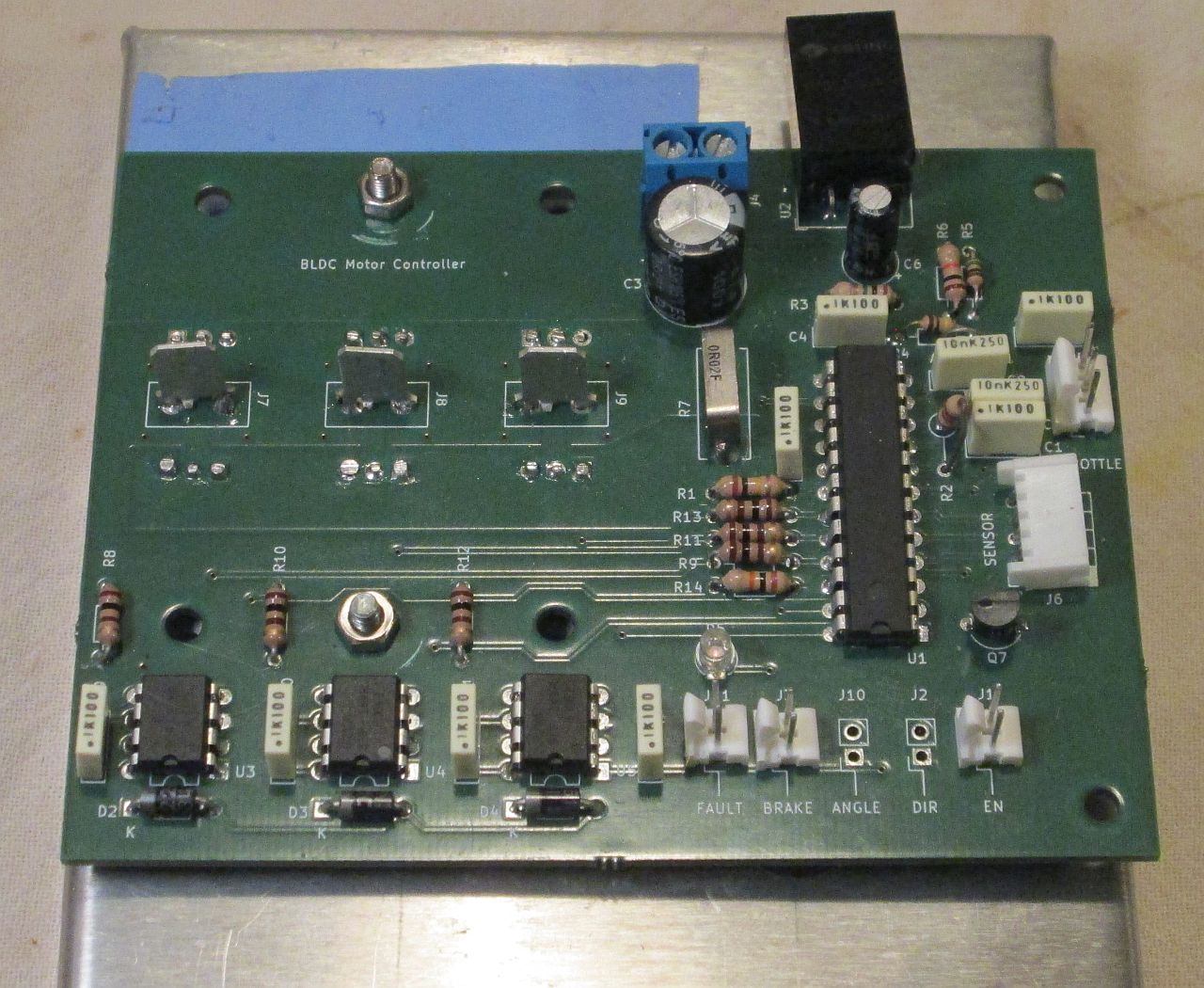
Building the BLDC Motor Controller
Everything went well, I’ve soldered far more complex boards. It took a few minutes to do, not including a last minute part order.

Always nice to have a real PCB for you projects.

Soldered up and bolted down to a temporary heatsink. I didn’t bother putting connectors on ANGLE or DIR because I don’t really need them right now.
That’s not to say there weren’t some problems. Because there are always some problems when I design PCBs. Always.
First, I got the connector for the motor sensors backwards. That doesn’t matter for the signals, but it sure does matter for the power connections. I solved this problem in a characteristically pragmatic way: I flipped the connector over and bent the pins the other way.
Maybe I’ll stick to top-down connectors from now on.
The other big cock-up was the 12V regulator. I was planning around one of these RECOM modules. Guess what the Great Semiconductor Famine made really hard to find? I ended up switching to this CUI Devices module which is basically the same thing. Unfortunately they have very slightly different footprints- RECOM has pins at the front, CUI has pins at the back.
I just ordered the right-angle module to work around that. A little hot glue keeps it held down.

Where there’s a will, there’s a way.
Since the CUI part is about half the price of the RECOM one, I probably should have just used CUI from the start.
Everything else fits fine, though the connectors for the controls should have been turned 90 degrees. That would give me more room for big IDC style connectors. Works fine for now.
Testing the BLDC Motor Controller
We come now to the part I dread most: plugging the circuit into live power. Normally I wouldn’t care so much, but when your project has a history of becoming impromptu pyrotechnics you get a bit paranoid.
I’m not an idiot- at least not one that doesn’t learn from past mistakes- so I used my bench supply first. That thing has current limiting, so if something blows out I’ll know about it before it gets out of hand.
Well, nothing exploded when I turned it on. That’s a good sign. Unfortunately nothing happened. I tried various combinations of EN, BRAKE, and the throttle. Nothing.
Probing with the multimeter and oscilloscope didn’t reveal much. The only real clue I had was the FAULT lamp stayed on. What does that mean? Let’s look at the datasheet:

1 is ruled out because I know the motor is giving correct sensor output. Just in case, I checked the live signals. No problem here.
2 is also easy to rule out by toggling the EN switch. I made sure it was set to 1 and stayed there.
4 was ruled out by simply measuring the supply voltage. +12V, as expected.
5 can be ruled out because nothing is happening. No current, no power, no heat.
That leaves 3. Measurements showed pin 9 was maybe 180mV, but you can’t always trust those numbers. The only surefire way to rule out 3 was to short pin 9 to ground. Doing so completely disables the current limiting.

Don’t try this at home, kids.
Disabling the primary safety cutout got things working. Looks like I put a 100K resistor in the spike filter. A more reasonable choice would have been 1K. No idea why I put 100K in; probably just a miscalculation.
At this point the motor would shudder and squeal a bit. If spun it would sputter though one or two revolutions. Knowing I had trouble with this before, I started swapping the phase wires around. That did the trick.
Well, not exactly. The motor only runs if you give it an initial push. BLDC motors should be self starting. Hmm.
A little research led me to conclude the bootstrap capacitors on the IR2118s were discharging. That wouldn’t normally be a showstopper though. They should charge back up when they get switched.
Then it all clicked together: the MC33035 PWMs the lower half of the bridge, but leaves the upper half either ON or OFF. The upper half of the bridge therefore is never switched except when the motor moves. Which will never happen on it’s own, since the upper switch needs to be ON to move the motor in the first place!
Fixing the Bugs
Fixing up the current sense voltage being too high is easy. I had put a 100K resistor in the spike filter. All I have to do is replace that with a smaller value resistor.
As for the drivers, I don’t have a ton of options. There does not exist a “self-exciting” IR2118 equivalent nor is there a MC33035 that has a top-up circuit. Attempts to jiggle the MC33035 in just the right way have thus far proven fruitless.
I have a pretty good idea how to fix the bootstrapping problem, but it’s going to take some time. I’d rather not hold this article back any longer; the fix-up will be detailed in a few weeks.
Update: I did, in fact, get things working eventually.
Finishing Up
Perhaps the most dangerous thing you can think is “that doesn’t look so hard”. Worse, follow it up with “I could do better”. You would think this would end badly, but the opposite happens just often enough to get you. BLDC drivers aren’t hard, but clearly more than I bargained for.
This project was less a triumph of engineering, and more an exercise in humility. Normally I wouldn’t publish a project that didn’t work properly. I feel the educational value overwhelms any personal shame. Knowing how to fix stuff is a crucial skill in any technical career. Learning from other people’s mistakes is just as important.
It may seem a little odd to say this on a site entirely dedicated to building your own stuff, but sometimes it’s not a good idea to build your own stuff. Part of engineering- and life in general- is learning when to use someone else’s solution. Clearly I’m not yet competent enough to build a high power inverter from scratch. Looking back, I’m not entirely sure if the scratch build is even worth it when the prefab IC ends up being about as good.
Thinking about it, the first two prototypes probably failed because I used underrated components. The difference between a 20V diode and a 100V one is often only one or two hard to read numbers. Said numbers are impossible to read if the part burns up.
My trouble with the MOSFET bootstrap is a good example of how a small oversight can completely break a project. There is nothing in either the IR2118 or MC33035 datasheet that indicates a traditional bootstrap circuit won’t work here. You just have to learn the hard way, and remember the experience for later.
A bittersweet ending, but not every story has (or should have) a happy ending. Building stuff requires both the pride to see a project through any problems, but also the humility to realize when a project is just fucked. Perseverance is trying new ideas that might work; stubbornness is sticking to one that doesn’t.
I had two projects in mind for this BLDC driver. One can work around the startup problem, and will likely be ready to show in a week or two. The other will have to wait for a proper solution to the startup problem.
Have a question? Comment? Insight? Post below!