Building A Proof Of Concept Card Reader From Junk
Sometimes a project comes to you not out of some necessary application, not out of idle curiosity, not out of “just for fun”, but rather because two things happen to come along simultaneously. As the descendant of two proto-hoarders, I too have accumulated a lot of random junk. Among that junk is a plethora of single-use gift cards. You know, the kind with a magnetic strip. I like having a few around because they’re handy as shims, scrapers, or just a source of sheet plastic.
I probably have dozens of these cards knocking about, and for all the “alternative” uses I have come up for them, never once did I consider using them as, you know, magnetic stripe cards. In a brief moment of idle thought, I remembered I have several tape heads lying around too. Magnetic cards are basically a kind of magnetic tape, if you think about it. Suddenly inspired, I started searching around for card reader schematics.
Turns out it’s actually pretty easy to rig up a simple card reader circuit to get the information off them. You don’t need much more than a tape head, a decent op-amp, and some standard components. A little tricky, sure, but not out of the realm of the amateur. Good enough for a first step proof of concept. Considering I never really do analog circuit design, it’s a good refresher of some of the more painful bits of analog design. I have forgotten more about op-amps than I ever thought I knew to begin with!
Magnetic Pickup Basics
The core of any magnetic card reader is the pickup head. Usually just referred to as a “tape head” or perhaps just “head”, this is a little horseshoe inductor that senses minute magnetic fields. In particular, it’s used to sense a change in magnetic field. If you’ll remember your basic electrical knowledge (look it up if you lack such knowledge, I’ll wait patiently) then you know that an inductor only produces voltage when exposed to a change in magnetic flux. Specifically as described by Faraday’s Law of Induction:

v is, of course the instantaneous voltage. PhiB is the strength of the magnetic field. d/dt simply implies a a change over time. While inductors are usually considered current-driven devices, in this case it turns out not to matter that much. You can always write current in terms of voltage, and vice-versa. We usually pick the one that makes the equations easier, so I choose to treat the inductor as a voltage source.
Magnetic tape stores information by recording a variable flux pattern to the tape. Using Faraday’s Law of Induction, this varying flux produces a voltage in the read head. In analog applications the flux is always varying. For digital applications, things are a little trickier. Typically a “line code” is used. A digital ‘1’ is represented by a transition, while a ‘0’ is represented by no transition. Both systems use the same kind of pickup- which means you can pull a tape head off an analog recorder to get digital information off a magstripe card.
Theoretically, you could build the tape head yourself. I mean, somebody had to build the first tape head using far less advanced equipment after all. Rather than go to all that work, I’d suggest getting tape heads from junked tape players. Heads vary considerably in their properties, including how many heads are in one unit, but so long as you get your hands on any tape head you should be good to go.

My particular heads came out of a very old tape recorder my local library was getting rid of a decade or so ago.
Every once in a while, I regret taking that thing apart. Then I remember I probably wouldn’t have done anything with it, until I finally threw it out.
Tape Head Amplifier
It should be noted, that the tape head produces very weak signals (often <1mV!). It may be necessary to use advanced low-noise techniques to get a reliable signal. Multiple amplification stages are usually used. Shielding may be required. This circuit produces a gain of 1,000,000 so even tiny signals will get amplified to the point where we need to deal with them.
I’d suggest using a high impedance input op-amp. Tape heads are very low impedance with very low voltage output. Higher input impedance means lower input voltages get picked up. The JFET input TL082 fits the bill pretty nicely, which is good because they’re already in my parts box.

Analog design is very much not my specialty. Waaayyy too much precision mathematics. Quite a bit of stuff you were only briefly told at university suddenly becomes relevant here. Not for the first time, I’m going to suggest looking into The Art of Electronics, 2nd Ed. (Horowitz and Hill, 1989). Specifically, Chapter 7: Precision Circuits And Low-Noise Techniques.
Analog signals are typically AC signals, which complicates how the circuit must be designed. DC bias on the tape head can erase data rather than reading it, so AC coupling the head is a good idea. Since the tape head has very DC low impedance it will also tend to short out your amplifier’s biasing networks.
Amplifiers are not magic, and they have limits just like anything else. What is particularly relevant to this circuit is the gain-bandwidth product (GBW). In simple terms, GBW means you can have lots of gain, or lots of bandwidth, but not both simultaneously. For the TL082, the GBW is clearly stated as 4MHz- this is the frequency where gain drops down to 1x. To get 1000x gain, we are therefore limited to about 4KHz of bandwidth. Bandwidth limits data density, so keeping bandwidth high seems at least somewhat important.
Another problem comes in the op-amp input circuit. Most of the time we can ignore things like input current, offset, and impedance. When you have tiny little signals well below these limits, you really need to account for it. Out of curiosity I replaced the TL082 with an LM358. It barely worked, and produced no viable output. Having those high impdeance JFET inputs is really important! I did not need to resort to T networks or trimming networks. This may not hold up in the future.
Having completed the schematic (I built the circuit first), and analyzed it in the way you can only analyze something written down, this circuit strikes me as very crude. I don’t like it that much. Getting this circuit working was less technical analysis, more blind luck. I clearly need to review analog design before doing anything more complicated.
Magnetic Stripe Card Reader Experiments
In the digital domain, you rarely need to do much experimental work. Digital circuits mostly Just Work. Meanwhile, analog circuits rarely, if ever, do what you want them to do. You’d surprised just how easy it is to build a radio receiver. Even if you’re specifically trying not to build one. Especially if you’re trying to do anything else.
By far the biggest issue I kept running into was 60Hz pickup from mains power. I concluded this was radiated noise, not conducted, because that 60Hz sine wave still showed up when I unplugged the power supply. Normally this signal is so faint, you can barely see it on your oscilloscope. Random noise ends up being far more noticeable. Unfortunately random noise tends to cancel itself out. Regular signals reinforce themselves. Remember, at 1,000,000x gain even 1mV will saturate the output.
Eliminating the 60Hz pickup was mostly trial-and-error. I put capacitors here and there, rearranged components, and rebuilt the basic circuit several times. Turns out being too fancy is not an asset. I got reliable results using the simplest circuit.
The other big confusion was remembering how single supply op-amps with virtual grounds work. Entirely my fault for not having done this kind of work in years. Again, the simplest possible circuit proved to be the most effective.
Having relearned basic op-amp circuits, I was able to reliably get cards scanned. I have nothing that can use this data (yet), but hey, I can get reliable data out.

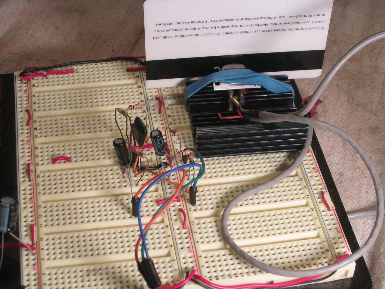
Breadboard circuits never look good. I needed to patch in some hasty modifications here and there. Those wires to the bottom left go to the tape head.
I should note that keeping the various leads short is important for noise control.

Cards have several tracks, so the vertical position of the head matters. This little heatsink just happened to keep everything aligned, with a convenient slot to slide the card in. I only came up with the rubber band after testing the circuit. Works much better than trying to hold the head down with your hand.

Preamp output is the lower, blue trace. Final output is the upper, yellow trace.
This particular sequence came off an expired gift card. I don’t really know enough to decode it properly yet.
A few notes for those who would try this on their own:
- Tape heads come in different impedances. Use the highest impedance head to read. It makes designing the circuit much easier.
- DC bias in the head can erase low-coercivity cards. I’d strongly suggest not using any card you rely on for this kind of experiment.
- Given the high-gain/low signal setup, it is critical to keep connections short and close. Keep EM radiators away (e.g. power transformers, switching supplies). Conducted noise can be a problem too- it may be necessary to use a linear power supply or batteries.
- Did you know the human body is a near perfect antenna for 50/60Hz mains hum? Don’t touch the circuit while it’s working. Good advice in general.
- Physical orientation is crucial. The card must contact the head, which in turn must be positioned over the track you’re trying to read. You may need to build some kind of support.
Finishing Up
My goal with this particular project was mostly just to get something out of the tape head. I didn’t really know if I could get the circuit working on a breadboard, with the bits and pieces I had to hand. There’s a lot to go wrong here. I’m happy to report you can in fact pull if off- albeit with some caveats.
While good enough as a proof of concept, there are a few big problems that need to be solved before going further. Thus far the circuit is entirely analog, since magnetic recording is inherently analog. Data on the card is represented digitally- so digital techniques will have to be used to actually understand said data. Given the complexity of the signal, it is doubtful that this can be done without a microcontroller.
I mentioned it before, I’ll mention it again: there is much improvement to be had in the analog design. In particular I’m interested to know if the pre-amplifier can use differential input. That would solve a lot of noise issues. Other ideas include switching to a different amplifier (something lower voltage ideally), using a comparator for the final output, and adding in a trimming network.
Writing new information to the card requires a similar circuit that’s effectively run in reverse. Since digital signals are inherently all-on or all-off, this could be as easy as directly piping the logic signal to the head. I suppose it depends entirely on how much current is required. I may have to run some experiments.
Magstripe cards usually have multiple tracks. Wider stripes imply more tracks. Two and three tracks are very common. To read different tracks, you need a head with multiple channels or a way to move the head vertically. For this experiment, I see no reason to get fancy. A basic shim will suffice.
Pretty much all magnetic storage media works the same way. Quite a few old storage devices used a similar head to write to disks or drums. I think the connection is pretty obvious; I have an idea in the works.
September rapidly comes to a close; a particularly unproductive month. I have several smaller projects ready to go, with the bigger projects having slow but steady progress.
Magnetics is a field I’ve wanted to experiment with for a while now. While I have some ideas for a magnetic card reader/writer, I’d like to also try some more unusual ideas with the same hardware.
Have a question? Comment? Insight? Post below!