Part 1: VGA Time Base Generation
Ever since I started designing computers, I knew I needed to come up with some kind of graphics interface. Preferably one that didn’t require specialty hardware, licensing, or only worked with very old displays.
There is one, and only one, interface that does the job: VGA. Despite being completely obsolete, VGA is still common enough it’s supported by new devices. Being the standard for a few decades, secondhand equipment that handles VGA is also cheap and plentiful.
Underneath the high level design, VGA is very approachable. You can easily make VGA signals with simple logic ICs. I’m far from the first to have done this. What’s less common is developing an actual graphics adapter. You know, something you could slot into a computer system.
But before getting into the actual computer-y aspects of VGA, the timing circuit must be set up. It’s a fairly straightforward project, upon which anything more advanced must sit. I’ve made a few semi-successful attempts at this in the past, but this is the first one that’s good enough to develop further.
The Big List
While there is no reason I couldn’t just post everything all at once, the developmental nature of this project means splitting it up into more detailed sections is a good idea.
- Time Base Generation- VGA requires a rock-stable timing chain to work. It therefore must be done first.
- Framebuffer and Bitmap Graphics- Without some kind of memory, you can’t display anything useful.
- Text Mode- A specialized graphics mode that allows for more compact representation of tiled graphics, i.e. text.
- Control and Interface- Adding the final bits of glue logic to hook into an external system.
I might tweak this list as things develop. I don’t really have a specific goal in mind other than proving the basics right now.
VGA Basics
Video Graphics Array (VGA) was invented by IBM as an all-in-one display control device. It was an integral part of the PS/2 computer. As in literally soldered to the motherboard. VGA stuck around for thirty-some years, almost unheard of in PC hardware, and still enjoys popular support today- much like another PS/2 interface.
While the VGA is supposed to be a single IC, it’s an iterative advancement over the discrete logic that came before. Building an all-discrete logic VGA compatible adapter is very easy. Well, as easy as graphics hardware gets.
Being a popular standard, VGA specs are easy to find. All of my designs are based around 800×600 “SVGA” specs. It is by far the easiest one to work with. Have a look at them over here for the full details.
One line of 800×600 VGA is actually 1056 pixels long, 256 of which are non-visible. Similarly there are 628 lines, 28 non visible. Synchronizing pulses occur during the non-visible area- you can think of them as special pixel/line patterns. This all made some sense when an analog CRT was doing the display work, and it continued to be mandatory long after it stopped being useful.
While there is technically no restriction on how frequently pixels are posted, anything vaguely modern is going to refuse to display a non-compliant signal. Even when CRTs were common, they frequently only worked with a small set of resolutions. Modern LCDs are far more picky because they have to sample the analog signal. You’ll be stuck with the basic resolution of a particular VGA clock. For 800×600, that means pixels can be changed every 50ns at the most.
Subdividing a resolution is possible, and in fact recommended because 800×600 is a lot. Simply print the same pixel/line multiple times inside the same timing. I’m aiming for 200×150, a mere sixteenth of the full resolution.
Color is a three-channel RGB signal. This is an analog voltage of 0-0.7V feeding a 75 ohm line. There is more lenience in the color being not entirely to spec, though loss of precision means things are still pretty limited. 256 colors would appear to be the practical limit.
VGA Timing Chain
All timing is derived from a master clock source and a two counter chain. One counter tracks individual pixels, the other lines. Functionally this is simply a divide-by-1056 counter cascaded with a divide-by-628 counter.
You can get big counters, but not all counters are created equal. Big counters usually skip a few outputs to minimize pin count. They’re also universally asynchronous. VGA time constraints require synchronous operation.
At first I wanted to use HC193 counters, but quickly concluded they didn’t work the way I wanted them to. Shame, I’ve been looking for some way to use them.
I then switched over to the HC163, which is a more suitable type. Full synchronous count, reset, and load. A little hardware trickery allows for separate master reset and counter reset. It simplifies the logic a little.

Both counters need 10 bits. I get an extra “hidden” bit of division by using a 20MHz source instead of 40MHz, but it doesn’t really amount to anything- HC163s are 4 bits wide, and I still need 9 bits. All the pixel lines are shifted down one position from where they “should” be. Theoretically you can cram as many (or as few) pixels into one line if the resulting line rate is still 37.8KHz. As I mentioned previously, this will likely cause display issues. Stick to the given pixel rate or even divisions thereof.
Counting lines requires no such special consideration because the line rate is still 37.8KHz. Unlike the pixel rate, the line rate is always contractual. Skipping lines will cause blank areas on the display, and counting slower or faster will simply distort the display- assuming it displays at all.
Generating the control signals is significantly more complex. These need to be active at precise times, which don’t really correspond to nice binary numbers. In the past, I’ve tried a lot of different solutions. None of them are particularly good.
Eventually I decided to just use a PLD. This has it’s own issues, mostly in the form of trying to get WinCUPL to behave. You don’t know what software hell is until you have to get 30+ year old software running on a modern machine.
The horizontal logic:
Name     VGADECODERH;
PartNo   ;
Date     ;
Revision ;
Designer ;
Company  ;
Assembly ;
Location ;
Device   g16v8;
/* *************** INPUT PINS *********************/
PIN 1   = A;
PIN 2   = B;
PIN 3   = C;
PIN 4   = D;
PIN 5   = E;
PIN 6   = F;
PIN 7   = G;
PIN 8   = H;
PIN 9   = I;
PIN 11  = J;
/* *************** OUTPUT PINS *********************/
/*Three outputs, HSYNC, HRSET, and BLANK*/
PIN 17  = BLANK;
PIN 18  = HSYNC;
PIN 19  = HRSET;
field count = [J,I,H,G,F,E,D,C,B,A];
BLANK = count:['d'400..'d'1023];
HSYNC = count:['d'420..'d'484];
!HRSET = count:['d'527];
And the vertical logic:
Name     VGADECODERV;
PartNo   ;
Date     ;
Revision ;
Designer ;
Company  ;
Assembly ;
Location ;
Device   g16v8;
/* *************** INPUT PINS *********************/
PIN 1   = A;
PIN 2   = B;
PIN 3   = C;
PIN 4   = D;
PIN 5   = E;
PIN 6   = F;
PIN 7   = G;
PIN 8   = H;
PIN 9   = I;
PIN 11  = J;
PIN 12  = HBLANK;
/* *************** OUTPUT PINS *********************/
/*Three outputs, VSYNC, VRSET, and BLANK*/
PIN 17  = BLANK;
PIN 18  = VSYNC;
PIN 19  = VRSET;
field count = [J,I,H,G,F,E,D,C,B,A];
BLANK = count:['d'600..'d'1023]#HBLANK;
VSYNC = count:['d'601..'d'605];
!VRSET = count:['d'627..'d'1023];
While not particularly complicated, WinCUPL crashes if you exist too hard. No, the error messages are not helpful. No, there does not seem to be a viable alternative to WinCUPL.
Also, if you do try this, make sure you know exactly what PLD you use. When my programmer uploaded in GAL16V8 mode, I got bizarre results. Switching to GAL16V8B mode fixed everything. Not the first time I’ve dealt with an extra letter in the part name causing trouble.
Notice how I’m chaining the horizontal and vertical blank signals together. It saves an extra OR gate. Blank is blank, regardless of which half of the signal requests it.
Output Test Circuit
Checking the output of the counters is easy, but I know from experience this isn’t indicative of whether a real monitor will actually work with the circuit. In practice, a minimal amount of extras is required to generate a color signal. This can further be used to check if the pixels themselves are correctly displayed.
Also it means I have something to show beyond a blank, black screen.

Exactly as easy as it looks. VGA expects a 0.7V signal with 75R termination. Through sheer happenstance if you put 470R in series with a 5V source, you get a little less than 0.7V on a 75R line. Good enough for a test.
I connected RGB to the low-order lines of the horizontal counter. This particular setup will divide the screen into vertical color bars. 25 sets of 8 to be precise. The same thing can be done with the vertical counter to produce horizontal lines.
You do need a high-density DB15F connector- like this one– to connect the monitor. Soldering wires directly to the connector pins is possible, but an adapter board is so, so much better.

This tiny PCB is SO HANDY.
Either way, the connections are nice and straightforward.
Testing the VGA Time Base
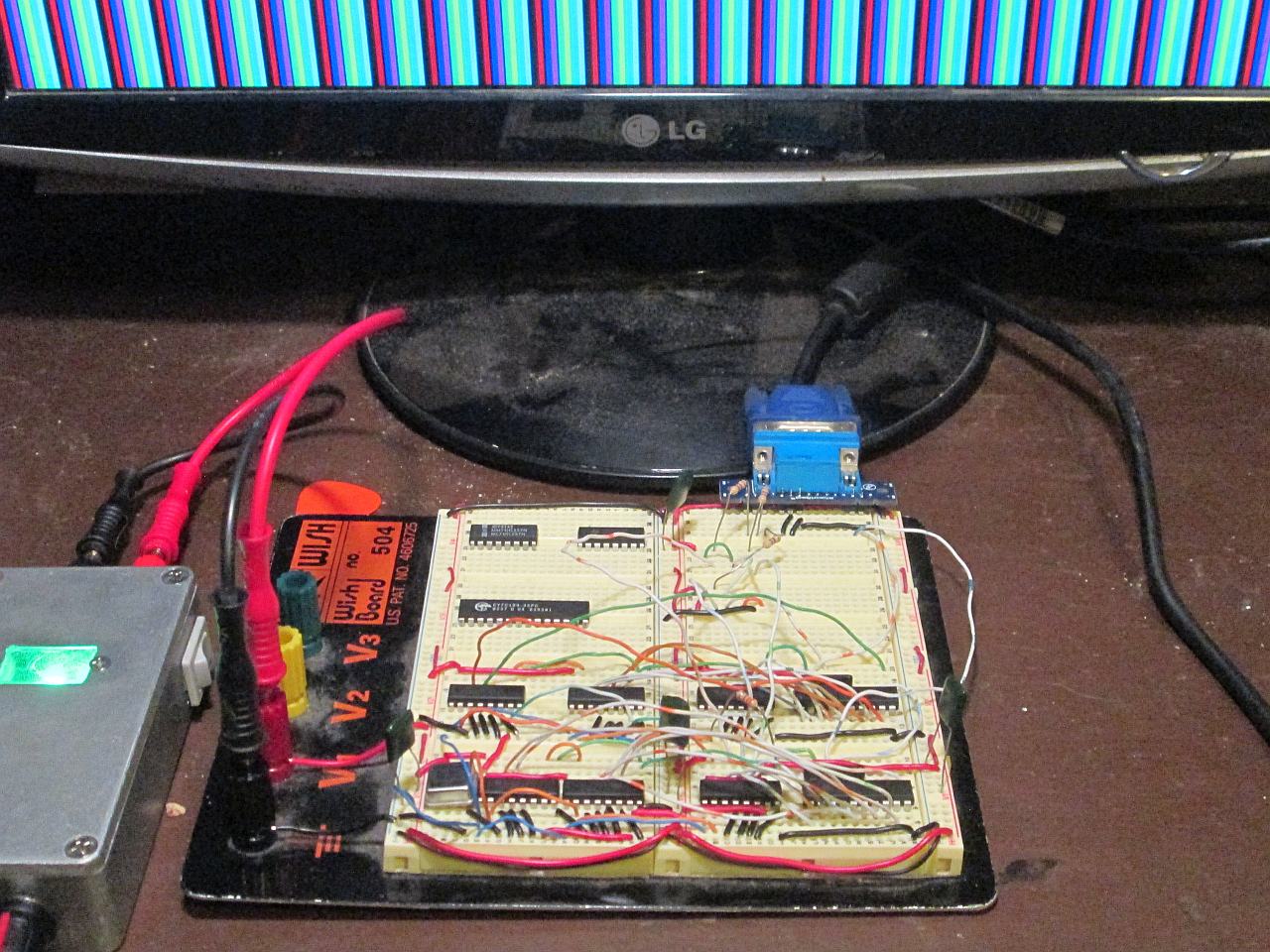
Being a prototyping project, it makes sense to start with a simple breadboard circuit.

Wire spaghetti, but it’s rock solid.
Horizontal counter on the bottom, vertical counter above that, output on the upper right.
Some folks say you can’t do 20MHz on a a breadboard. Those folks are wrong. It’s true that a breadboard adds extra capacitance and long wires are good noise conductors. However, a 5V digital signal is extremely tolerant of both. Furthermore if you bother analyzing the circuit you’ll see that only the horizontal clock inputs are running at 20MHz. Everything else is 10MHz or less. Signal integrity might cause some issues down the line, but for now it’s not worth worrying about.
I did discover that GAL output is extremely glitchy. It wouldn’t be a problem if it didn’t cause a double transition on the vertical clock input. I added a 330R into the horizontal reset/vertical clock line to counteract this. Works okay for now; might need tweaking later. GALs also seem to struggle with positive voltage drive. I threw on a 1K pull-up resistor to fix the issue.
Okay, it’s time for the big test. Plug the circuit into a monitor, see what happens. This particular one is old and unused, so if it blows out I’m not too fussed.

Vertical color bands using pixel counter to drive the RGB output.

Horizontal color bands using the corresponding line counts.

Vertical close up.
It took a few days to work all the bugs out of the circuit, but when I did finally plug the monitor in it worked perfectly.
Okay, I had to move one connection and dispose of a newly redundant HC08 before it looked like that picture. That’s so minor. There were color bars in the expected pattern, and that’s what really matters.
Finishing Up
Compared to some of my earlier attempts, this VGA time base came together over a few days. Most of the struggle ended up being getting the GALs to behave properly. Once I realized the difference a trailing B could make, they worked more or less as expected.
Getting a stable image displayed is only the first step. Right now the circuit is only useful for checking if an old monitor works properly. Adding the extra parts to display actual graphics is the next step- a step a little too complex to stuff in the same article.
One intriguing possibility for further development is to support several different timings. This would allow switching between different resolutions e.g. 640×480 and 800×600. To support this, multiple master clocks would need to be generated, and the counter logic would have to be more complex. I can see how to do it, but I don’t really have a good reason to go further right now. Perhaps I should revisit it later.
Using PLDs shortens the design time considerably. They also save space by combining multiple logic circuits in one package. I would consider using only simple gate logic, but the lack of good options makes things too hard.
Originally I thought I needed to shut off the color signal during the blanking period. Turns out it might be optional. In practice though, it’s going to be necessary to interface with a CPU.
Except for the GAL configuration snafu, things went broadly as expected. Good, because this is the boring drudgework that has to be done before we can get to the interesting stuff.
Next time, memory will be added to allow something more than simple lines to be displayed.
Have a question? Comment? Insight? Post below!