Writing The KERNAL Of A 6502 OS
One of the goals I have with 6502 development is to write my own custom OS that can run on any 6502 hardware I can throw at it. Operating systems are hella complicated, and it was obvious to me from the beginning that it would require lots of work. Lots of work, parceled over a long set of articles. Might as well start today, with the basic foundation: system calls.
An operating system serves two, not entirely overlapping roles: managing system resources and abstracting/extending the hardware. Resource management is not particularly interesting for a single-tasking OS, so I won’t talk about that for a while yet. Abstracting and extending the hardware on the other hand, is very useful regardless of what the upper layers look like. It’s the logical starting point- in more ways than one.
Modular Monitor is not an OS per se, but it has the basic infrastructure to act as one. By abstracting MM’s low level routines into system calls I can begin to separate the OS level details from user level programs. Future development will become easier as a result. No more re-invented wheels, no more hand patched hacks, no more reverse engineering my own ROM files to find function entry points. Just a handful of easy to remember calls.
With the low level system calls factored out, you can focus on the big interesting programs you actually want to write. Even if you’re one of those weird people who exclusively programs bare metal systems in raw assembly, system functions are still very useful!
Part of the Modular Monitor Series:
- Modular Monitor: Serial Terminals, Hardware Bugs, and You
- Modular Monitor: a Flexible ROM Monitor for the 6502
- Modular Monitor: Dynamic Dispatch and Code Cleanup
- Modular Monitor: Interactive Debugging With The Non Maskable Interrupt
- Modular Monitor: Porting To The Single Board Development System
- Modular Monitor: Operating System Call Table
Modular Monitor System Call Table
Much of this design comes directly from the Commodore 64 KERNAL calls. Hence, the reference in the subtitle. KERNAL uses a fairly clever trick to allow the 6502 to perform an indirect subroutine call without jumping through too many hoops. Since the 6502 does not have an indirect call instruction, that’s a problem worth solving.
The solution is to put a jump table in a fixed, known location in memory (typically in ROM). Table entries point to service routines. Since the table is in a fixed order, we simply hardcode the addresses associated with each system call. I don’t like it much, but it’s the least bad solution. The 6502 makes me think that a lot.
A Tale Of Two Tables
In order to make this idea work, the jump table must be broken into two separate tables. This is necessary because the 6502 does not have an instruction set that easily supports a one table solution. Such is life with the 6502.
One table is fixed in ROM or some other guaranteed location. These are nailed down to permanent addresses. Each entry is simply a JMP (ABS) instruction. Indirect jumps can be thought of as jumping through the given address, rather than to said address. Decoupling the addresses this way allows for dynamic control redirection, without resorting to self-modifying code. Well, sort of. You don’t have to modify the JMP instructions themselves, so it counts even if it doesn’t quite feel like it.
The other table is in a pretty arbitrary location. It doesn’t even need to be a table; each entry could be in any random location. In practice, organizing it as a table is easier on everyone. Each entry is a two byte address to the real target of the JMP (ABS) instructions. By putting this table in RAM entries can be edited at runtime.
To access these functions, you JSR to the JMP (ABS), then vector through the second table automatically. JSR is required for any function expected to return, because the 6502 does not let you save a return address in any other way. This technique imposes a 6 cycle penalty over a simple JSR. A cost well worth paying.

How a system call using this method works.
This may seem like a very roundabout way to get somewhere, but it’s a very common pattern in programming.
A lot of this faffery could have been avoided if the 6502 had a JSR (ABS) instruction. As far as I know, no 6502 based CPU does.
System Calls
I broke the system calls into three broad categories: I/O control, process control, and miscellaneous utility functions. They are all broadly based on existing parts of Modular Monitor.
I/O control, naturally, refers to low-level device control. Right now I’m keeping things simple, so only the UART is getting any love. Don’t fret, because the VIA uses a nearly identical interface. Swapping them will not be hard. I have other plans for how to handle I/O, so this is only temporary anyways.
- GET, PUT– Send bytes to/from the currently selected I/O device (defaults to UART)
- PRINT– Send a NULL terminated string to the currently selected I/O device
- IRQ, NMI– Handlers for the interrupt routines
Process control is somewhat limited because Modular Monitor can only run one thing at a time right now. When I eventually get around to multitasking this set will get a lot bigger.
- QUIT– Stop the currently running program, freeing any resources it might have used
- EXEC– Start a new thread of execution
What’s left goes into the basically random utility section. This is everything else I felt like adding a call for, but don’t fit anywhere else.
- HEX2BIN, BIN2HEX, NIB2HEX, HEX2NIB– Conversion routines required for many Modular Monitor functions
All of these functions can be re-targeted at runtime. There’s room for a whopping 83 system calls, so adding new ones won’t be a problem for some time. Possibly ever.
Implementing System Calls In 6502 Assembly
I think it’s fairly obvious how to implement the system calls. Each fixed JMP (ABS) instruction points to a fixed location in the secondary vector table. You load the actual handler address into this second table. There is no need for any special handling beyond finding the addresses.
For the fixed table of JMP (ABS) instructions, I chose to put them at $FF00. Each call requires three bytes, so it’s possible to squeeze 83 entries in. If that seem to come up short, don’t forget the 6502 puts the interrupt vectors in the last six bytes ($FFFA-$FFFF). ca65 doesn’t like absolute code, so I had to add a special segment to the linker to insert the table at the correct location. Less advanced assemblers have it easier; a simple ORG will be adequate.
.segment "KTAB"   ;ca65 segment address, $FF00 in actual hardware
JMP (VEC_TAB)     ;IRQ handler
JMP (VEC_TAB+2)   ;NMI handler
JMP (VEC_TAB+4)   ;GET data from I/O
JMP (VEC_TAB+6)   ;PUT data into I/O
...               ;Many more to come!
JMP (VEC_TAB+166) ;Last entry at $FFF7
Deciding on where the RAM resident table goes is a little more arbitrary. Each entry is only two bytes, so it only takes up 2/3 of the space. KERNAL put this table at $0300. I chose to do the same- this is where I’m putting system memory anyways.
Unlike the ROM resident table, this table has to be initialized from a third table of default addresses. I chose to hand code this bit instead of turning it into a system call. KERNAL had a call that let you update the entire table all at once; that could be useful later on. Right now I just don’t see the use case.
;Default table of handlers in ROM
.RODATA
VEC_DEF: .addr NO_INT, INIT, UART_RD, UART_WR, MON_MAIN, PRINT, HEX2BIN, HEX2NIB, BIN2HEX, NIB2HEX

;Startup copy routine to initialize the vector table in ROM
;Strong candidate for a future system call
.CODE
LDA #>VEC_DEF
STA RD_PTR+1
LDA #<VEC_DEF
STA RD_PTR      ;Load the addres of VEC_DEF into the read pointer
LDA #$03
STA WR_PTR+1
STZ WR_PTR      ;Load $0300 into the write pointer
LDY #VEC_LENGH  ;Length of VEC_DEF
@LOOP:
LDA (RD_PTR), Y
STA (WR_PTR), Y
DEY             ;Counting backwards is slightly easier
BPL @LOOP
...             ;Continue to the rest of your regularly scheduled programming
As for the system calls themselves, they are currently identical to the existing routines in Modular Monitor. There is no need to change them yet. Since they can be changed at runtime, there is no need to reprogram the ROM to add a new call.
System Call Demonstration(?)
This is unfortunately not a project that lends itself well to a demonstration. I did re-write many of the modules to use the system calls, but they don’t work any differently from the existing routines. Ironically they’d only produce interesting results if they didn’t work properly!
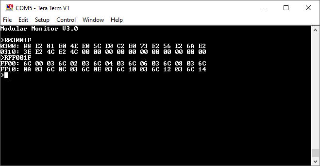
Instead, I’ll show some internal data related to the calls. Look, I don’t have much else to go on here.

$FF00 is where the JMP (ABS) instructions live. You can spot them by the opcode $6C. $0300 is where the actual handler addresses live. Right now they all point to the ROM at $Exxx.
Notice that READ now prints an address prefix on each line. Just one of the minor improvements I made during the rewrite.

Since system calls are just obfuscated JMP instructions, so they can be triggered by EXEC like any other executable code. Right now $FF03 points to the initialization routine at $E081. $FF03 is the NMI handler, so pressing the NMI button on my development board resets the system.
Finishing Up
Low level programming is full of unpleasant things. Even without the 6502’s obtuse instruction set you have to deal with address calculations, device drivers, and general annoyance. When you add the 6502 stuff into the mix you will take any assistance you can. Separating the low level programming from the high level stuff means I get to do more of the latter.
Now that I have my eyes on a proper OS, Modular Monitor’s time is rapidly coming to an end. With the low level stuff broken out into easily accessible calls, it is no longer necessary to actually edit MM to add new functionality. Anything I could want as a new module can now be written on top of MM. All the modules of MM will be rewritten into independent programs that are run when needed. This is the way a proper OS handles such things.
My primary reason for developing this stuff now is that I have several 6502 projects that don’t gel well with the way Modular Monitor is currently set up. It’s much easier to do things like redirecting I/O when you’re only dealing with a single fixed entry point. I also don’t fancy reflashing the ROM during development anymore. You only get a finite number of erase/program cycles after all.
Getting Modular Monitor running with the new system calls proved unusually difficult. Since I had to do some invasive refactoring anyways, I ended up redoing a lot of stuff from scratch. On the plus side, Modular Monitor is now rock stable. It would appear that my initial assumption of a lurking hardware bug is not true (hopefully!). I just didn’t catch all the software ones.
I put handlers for NMI/IRQ in the system call table because the 6502 hardware makes them difficult to retarget. Getting the 6502 to handle more than one interrupt has been on my to-do list for some time now. I can now experiment with that at my leisure. Interrupt retargeting is mandatory for hardware development too- something I have been working around for far too long.
Thus ends the third (and likely final) major refactoring of Modular Monitor. I’ll still need to add new calls from time to time, but that is largely behind me now.
Next, the upper layer of Modular Monitor will be converted to a shell. That’s the part of the OS that handles finding, loading, and executing other programs. Before that though, there’s lots of other infrastructure to contend with. I did say this would require a lot of work parceled out over multiple articles!
Have a question? Comment? Insight? Post below!