Building The Carriage Right The Second Time
It’s no secret that Scribble’s carriage was slapped together out of poorly designed parts. I started the carriage build very early on, well before I had a good idea of the complexities involved. Various kludges were implemented until it mostly worked. My hasty decisions have now come back to bite me.
While I wanted to push this back until Scribble was mostly complete, the pen changer turns out to require a much higher degree of mechanical precision than I initially expected. My original design was completely inadequate. Too slow, too wobbly, too inaccurate. I knew I would have to replace it at some point. Now is that point.
Of course the carriage itself is quite crude. I did not align the bearings well, leading to trouble with binding. Said bearings are nearly impossible to remove, because I put the mounting bolts on the bottom. Hey, it seemed like a good idea at the time. The belt isn’t well aligned, the carriage itself is too big, I stubbed my toe this morning, and my coffee is cold. Now that I’ve gotten my fill of petty complaints, it’s time to do something about them.
A total rebuild is required. Now that I have a better understanding of the mechanics (and a 3D printer), this is feasible. I ended up keeping the overall design, but there’s plenty of improvements.
Part of the Scribble Pen Plotter Series:
- Scribble Pen Plotter: The Mechanical Parts
- Scribble Pen Plotter: The Electronic Parts
- Scribble Pen Plotter: The First Functional Tests
- Scribble Pen Plotter: The Serial I/O Driver
- Scribble Pen Plotter: Rebuilding The Carriage
Scribble Plotter Carriage Rebuild
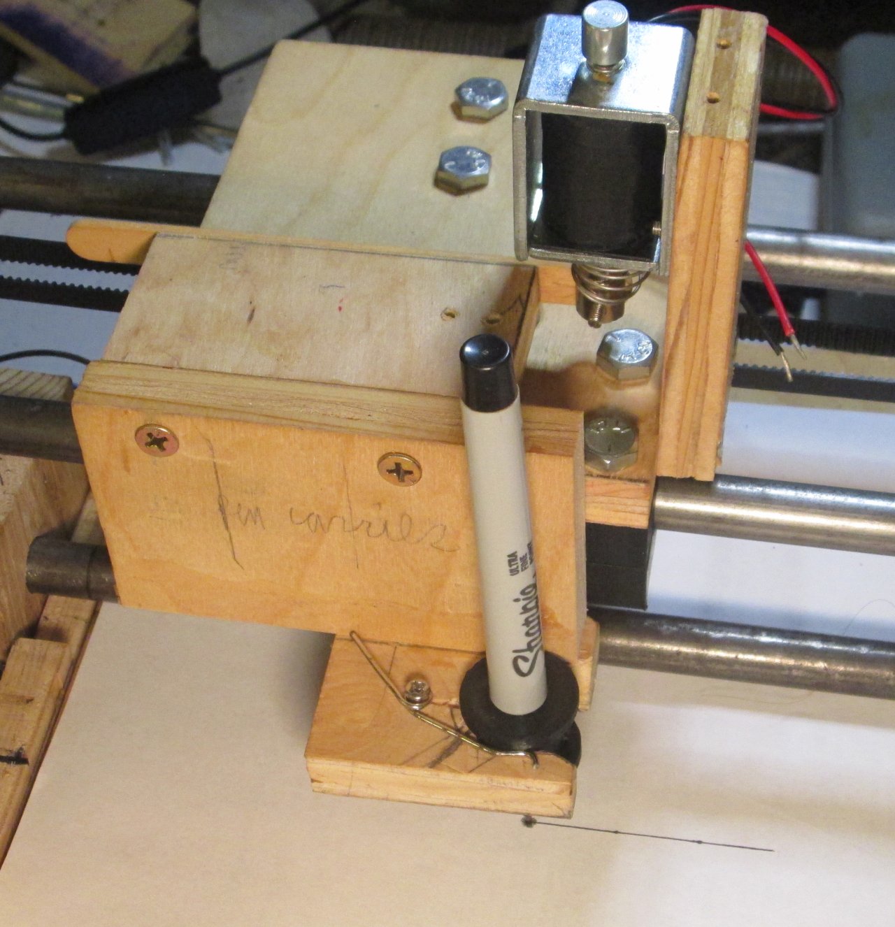
Scribble’s current carriage is useful, because it shows me exactly how not to build the new carriage. The horizontal bearings are prone to binding, impossible to access, and very difficult to trim. Hinging the pen lift causes all kinds of trouble with properly aligning the pen, as well as being simultaneously too loose (back to front) yet somehow too stiff (up and down).

While it looks pretty professional, this design is a janky piece of shit that barely works.
Both mechanisms need to be replaced. Other problems I have with the carriage (e.g. belt misalignment) can be fixed along the way.
Horizontal Motion
The original carriage had split-block bearings made from hardwood. Despite the design working on less complex projects, this time around they were very difficult to align. I don’t think it helps that I decided to put a big gap between the blocks. I’m still not quite sure what I was thinking. This design feature/flaw has caused me no end of troubles.

To this day, I don’t know why I thought this particular design was a good idea.
To solve this problem, I designed and printed some self-contained bearing blocks. PLA is not the best choice of material, but it has proven to be adequate. A three bearing design was chosen to minimize alignment issues.

Three bearings work fine for light duty motion. You can always form a triangle between any three points; trying to make a rectangle out of four points is maddeningly difficult.
These new bearings use captive nuts, with through bolts mounted from the top side of the carriage. With careful design the exposed bolt heads won’t cause trouble for the vertical motion. Putting them on the top means they can be adjusted using a standard nut driver. I now have much more clearance on the bearing bottom, which was also a persistent problem.
Vertical Motion
I went through several designs of pen lift before settling on the current hinged variation. This was mostly because linear designs failed due to precision woes. Once again, running holes through wood proved to be more trouble than it was worth. Hinges never worked very well, but they were the only viable mechanism at the time.

You can see the holes at the ends of this prototype pen holder. They are too far apart, and not nearly long enough to get a good linear action. As for the bolts guiding the gripper, they suffer similar issues.
3D printing neatly solves the production problems. You can typically trust printed parts to be reasonably accurate. But there are several problems that still need to be solved. At first, I tried a two-rod bearing similar to the carriage:

Initially promising, but ultimately unworkable. This was far from the only alternative design I tried, but the only one that was even remotely feasible.
A disappointing failure. There are still problems with mechanical alignment. Also, I never came up with a decent lifting mechanism. Solenoids are chunky. Solenoid alternatives proved even less suitable. At least the hinged lifter didn’t require an elaborate linkage.
At this point, I started wondering if the hinged design could still be made to work. My two main complaints are that it’s difficult to align, and has too much motion just to lift the pen. Those aren’t necessarily unsolvable.

Very similar to the original design, yet distinctly different. You know, in the ways it actually matters.
All that work, all those failed alternatives, just to end up back where I started. This time around, I have a rigid wooden lever that can’t melt, coupled with a single hinge that’s easier to align. Everything got trimmed down to miniaturize the mechanism. Not much of a change in the grand scheme of things. Still works better.
The only downside is that I need more horizontal clearance for lifting the pen. I need to redesign the pen carousel anyways, so I decided to keep the hinged design. Because I’m working on them simultaneously, I know for fact it will be much easier to fit the carousel to the carriage, not the other way around.
Installing The New Carriage
Retrofitting the new carriage is pleasingly straightforward. Outside of a few relatively accurate holes, there is no need to put much effort into the layout job. Installing the hinge is the trickiest bit. Misalignment will cause trouble later on.

Putting the bearings on is now a trivial action. Put bolts through the top, align with the bearing, and tighten up. Shims keep things the right distance apart for smooth sliding action.

One hinge is a lot easier to deal with than two. It barely fits, but it’s good enough.

I kept the solenoid at the side because it really can’t go anywhere else. I know because I tried.

Despite being the same overall design, the new carriage assembly is smaller, smoother, and just better than my first attempt.
Testing shows this is a fairly reasonable design. I still have to work out some issues with rigidity and how the pen carousel works- but those are issues for another article.
Finishing Up
Despite assurances to the contrary, Scribble is not done by the end of August. Or September. Or October. Or 2023. That’s just the way it goes sometimes- I’ve had a lot of real-life baggage to work around. Getting back into an old project is sometimes troublesome, but a great source of comfort. No pick-me-up like a sudden breakthrough on a tricky problem.
Split bearings are simple to build, but tricky to get right. 3D printing helps, though I have had success with hand-scraped wood block bearings. Aligning them properly is the hardest part. I strongly recommend using indexing jigs. Bolting the bearings greatly reduces assembly effort. It also allows for a small degree of misalignment tolerance.
Moving the pen up and down is by far the hardest challenge Scribble has thrown at me. Lots of problems have revealed themselves as I tried out various alternatives. A simple up/down motion seems like it ought to be the easiest solution, but it turns out to be way hard. Hinging the pen, while not perfect, ended up being the only viable solution.
Professionally produced plotters- including the HP7475A, which Scribble loosely copies- have a better solution to the pen lift. Turns out they rotate the entire guide rail assembly. This keeps the carriage/head small and simple. Really wish I figured that out before starting. Theoretically Scribble could be retrofit this way, but it would require a re-design of how the guide rails work. Future machines using a similar mechanism are a possibility.
At one point I had the idea of replacing the solenoid with a linear motor. There are some potential advantages to doing so. Solenoids are binary devices; they’re either in or out. Linear motors allow for a much finer degree of positioning. Where this could be advantageous is that “breaking” a drawn line only requires a very small movement- perhaps as little as 3mm or less. I know from other experiments that the fastest my solenoid can go is about 10Hz. Using a linear motor would greatly increase the drawing speed where many pen up/down sequences are used in rapid succession. Notably, HP-GL supports software-driven dotted and dashed lines.
What’s Next?
I didn’t plan to rebuild the carriage until after Scribble was functionally complete. As is so often the case, I ended up having to do the later parts of the plan sooner. The two big things that still need to happen are the HP-GL interpreter and the pen changer.
The good news is the basic HP-GL software is mostly complete. I can draw lines between arbitrary points, which sounds considerably less impressive if you aren’t a programmer. My main point of contention is writing the interpreter. Programming is always kind of boring, and I gradually lost interest in working on it while other bits of Scribble were unfinished. I’m going to have to pick that up again soon.
Of course, the main reason I even did this was to get the pen changer working. I have made significant breakthroughs over there. Given the complexity of the mechanism, I suspect it will be a two-part article.
Scribble continues to be the most challenging project I’ve taken on. Robotics is a tricky field with plenty of cross disciplinary knowledge required. Wood is not easy to work with precision. 3D printing greatly eases the burden of making precision parts. Use the right tools for the right job!
I’d like to finish Scribble up soon(ish) if only because it takes up a lot of table space. As the weather warms, I think I’ll make Scribble my “primary” project for the first part of 2024.
Have a question? Comment? Insight? Post below!